
ELEC-330 · Lesson 3 of 12 · 24 min
Control power, DC supplies and solid-state switching
Almost every modern control panel runs on 24 V DC: PLCs, sensors, relays, pilot lights, safety relays, network switches and HMIs all expect it. The quality of that control power, how it is generated, distributed, protected, grounded and kept free of noise, determines whether the control system runs reliably for years or suffers mysterious resets, flickering inputs and damaged modules. Control circuits also switch loads, sometimes with electromechanical relays and contactors and increasingly with solid-state devices. This lesson covers control transformers and AC control power, switch-mode DC power supplies and their sizing, distribution and protection of 24 V DC circuits, voltage drop on long control runs, grounding and noise, coil suppression, solid-state relays and their characteristics, surge protection, and the code and standard requirements for control circuits and industrial control panels.
AC control power
Many motor control circuits still run at 120 V AC, supplied by a control power transformer (CPT) in each starter or panel stepping down from the line voltage. CPTs are sized for the sealed VA of all coils plus the inrush VA when coils pick up, which can be five to ten times higher; an undersized CPT lets the voltage sag during inrush, so contactors chatter or fail to close. CPTs are protected by primary fuses and a secondary fuse, and one side of the secondary is normally grounded so that a ground fault in the control circuit blows the fuse rather than energizing a coil unexpectedly (ELEC-310).
Switch-mode DC power supplies
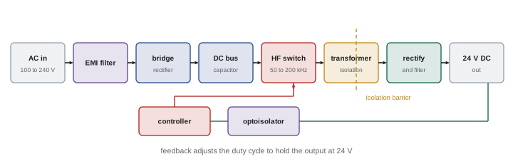
DC control power comes from switch-mode power supplies (SMPS). An SMPS rectifies the AC input, switches the resulting DC at high frequency (tens to hundreds of kilohertz) through a small transformer, then rectifies and filters the output, regulating it by adjusting the switching duty cycle. Compared with older linear supplies, SMPS units are much smaller, lighter and more efficient (often 90 % to 95 %). Industrial DIN-rail supplies offer wide input ranges (for example 100 to 240 V AC or three-phase 400 to 500 V AC), adjustable output voltage, a "DC OK" relay contact, and power reserves or boost currents to start loads and trip downstream breakers.
Selecting a supply involves:
- Load current: the sum of all loads, with allowance for inrush (capacitive inputs, lamps, motors, solenoids) and future additions, typically sizing the supply so normal load is 50 % to 80 % of its rating.
- Input: voltage, phases and the inrush current the supply draws at switch-on, which affects upstream breaker selection.
- Environment: ambient temperature derating, mounting orientation and spacing for cooling.
- Redundancy: for critical systems, two supplies feeding a redundancy module (with diodes or MOSFETs) so either can carry the load.
- Hold-up time: the time the output stays up during a brief input interruption, typically 20 ms or more; DC UPS modules with batteries or capacitors extend this for critical controllers.
Distributing and protecting 24 V DC
A single power supply often feeds dozens of circuits. A short circuit on one sensor cable should not take down the whole control system, so DC distribution is divided into protected circuits using:
- Miniature circuit breakers with DC ratings, but note that a supply limiting its output current may not deliver enough current to trip a standard breaker quickly; breakers with low magnetic trip settings or supplies with boost current are needed.
- Electronic circuit protection modules, which monitor each output channel and switch off the faulty channel selectively and quickly, often with remote reset and diagnostics.
- Fuses in terminal blocks for small circuits.
Good practice separates circuits by function: PLC and processor power, inputs, outputs, field sensors, safety circuits, and networks, so faults in field wiring do not crash the PLC. The 0 V side is distributed on clearly identified terminals, and wire colors follow the panel standard (for example dark blue for DC control conductors in many panels).
Voltage drop on control circuits
Low-voltage DC circuits are sensitive to voltage drop. A 24 V device with a minimum operating voltage of 19.2 V (−20 %) can tolerate a 4.8 V drop at most, but supply tolerance and connections use some of this margin. Long runs to remote sensors, solenoid valves and beacons need conductor sizes calculated for drop, not just ampacity.
Worked problem
Voltage drop to a remote solenoid valve
A 24 V DC solenoid valve draws 0.5 A and is 120 m from the panel. The cable is 1.0 mm² copper (about 18 AWG, 18.1 Ω/km). The supply is set to 24.0 V. What voltage reaches the valve, and is it within a −10 % tolerance?
Show solution
- Round-trip length: 2 × 120 = 240 m = 0.24 km.
- Resistance: 0.24 × 18.1 = 4.34 Ω.
- Drop: 0.5 A × 4.34 Ω = 2.17 V.
- Voltage at the valve: 24.0 − 2.17 = 21.8 V, which is above 21.6 V (−10 %), but only just.
- Options: raise the supply output to 25 V, use 1.5 mm² (16 AWG) cable, or relocate the I/O closer to the valve with remote I/O.
Answer: About 21.8 V, marginal. In practice, use a larger conductor or remote I/O to leave a margin for connections and supply tolerance.
Grounding and noise in control systems
Electronic controls are sensitive to electrical noise from drives, contactors, welders and radio transmitters. Noise couples into control wiring through shared conductors (common impedance), electric fields (capacitive coupling), magnetic fields (inductive coupling) and radiation. Good practice includes:
- Bonding all panel metalwork, DIN rails and back plates with low-impedance connections; zinc-plated back plates rather than painted ones for good contact.
- Deciding deliberately whether the 0 V DC is grounded (common in North America for safety and fault detection) or floating with insulation monitoring, and grounding it at one point only.
- Separating power and control wiring: different ducts or at least 200 mm spacing, crossing at right angles.
- Using shielded cable for analog signals and networks, with shields terminated as the manufacturer specifies (often at one end for analog signals, both ends with 360° clamps for drive motor cables and some networks).
- Twisted pairs for signals and DC circuits to reduce magnetic pickup.
Coil suppression
When a relay or contactor coil is de-energized, its magnetic field collapses and produces a voltage spike that can reach hundreds or thousands of volts. The spike arcs across switching contacts, wears them, and radiates noise that disturbs electronics; it can also destroy transistor outputs. Suppressors limit the spike:
- DC coils: a freewheeling diode (simple and effective, but slows dropout), a diode with a Zener (faster dropout), or a TVS diode.
- AC coils: an RC snubber or a metal-oxide varistor (MOV) across the coil.
Many contactors and relays accept plug-in suppressor modules. Suppression is particularly important when coils are switched by PLC transistor or triac outputs.
Solid-state relays
Solid-state relays (SSRs) switch loads with semiconductors instead of contacts: triacs or back-to-back SCRs for AC loads, MOSFETs for DC loads, with an optoisolated input. They have no moving parts, switch silently and quickly, last for millions of operations, and are ideal for frequent cycling such as heater control with PWM or zero-cross switching. Their characteristics differ from electromechanical relays:
- They have an on-state voltage drop (about 1 to 1.6 V for AC SSRs), so they produce heat and need heat sinks rated for the load current.
- They have off-state leakage current (a few milliamps), enough to keep some small loads, such as LED lamps or PLC inputs, partly on.
- They usually fail shorted, so the load stays on; safety functions must not rely on an SSR alone.
- Zero-cross SSRs switch on near voltage zero, minimizing noise for resistive loads; random-turn-on SSRs suit inductive loads and phase control.
| Feature | Electromechanical relay | Solid-state relay |
|---|---|---|
| Switching life | Hundreds of thousands to a few million operations | Practically unlimited if within ratings |
| Voltage drop and heat | Very low | About 1 to 1.6 V; needs heat sink |
| Off-state leakage | None (open contacts) | A few milliamps |
| Typical failure | Contacts weld or fail to close | Usually fails shorted (on) |
| Speed and noise | Milliseconds; audible click; contact arcing | Fast; silent; no arcing |
Surge protection
Lightning, utility switching and large motor switching produce surges that can damage electronics. Surge protective devices (SPDs) at the service, distribution panels and control panels divert surges to ground, with MOVs or gas discharge tubes, and signal-line SPDs protect long communication and analog cables between buildings. SPDs must be installed with short, straight leads to be effective, coordinated in levels from service entrance to equipment, and checked periodically, since MOVs degrade with each surge.
Codes and standards for control circuits
In the United States, NEC Article 724 (Class 1) and Article 725 (Class 2 and 3 power-limited circuits) govern remote control and signaling circuits, with Class 2 circuits from listed power-limited supplies permitting reduced wiring methods. Industrial control panels are listed to UL 508A, NEC Article 409 requires their short-circuit current rating (SCCR) to be marked, and NFPA 79 covers industrial machinery electrical equipment.
Short-circuit current rating matters for control panels: the panel's SCCR, determined by its components and their protection, must be at least the available fault current where it is installed, just as for distribution equipment (ELEC-320).
Control panel layout
A well-laid-out control panel is easier to build, test and maintain. Common practice places power distribution and incoming supply at the top, followed by motor starters and drives, then PLC and control components, with terminal blocks for field wiring along the bottom or sides. Heat-producing devices such as drives and power supplies are positioned so their heat does not flow over sensitive electronics, and enclosure cooling (filtered fans, air conditioners or heat exchangers) is sized from the heat load and the maximum ambient temperature. Wire ducts are sized with room for future wiring, typically no more than about 60 % full.
Every wire is identified with a number matching the schematic, every device is labeled with its designation, and the panel carries the required nameplate information, including voltage, full-load current, short-circuit current rating and the diagram reference. A copy of the as-built drawings stored in the panel or available electronically saves hours during troubleshooting. Panels built to a recognized standard and certified by the shop or inspected in the field are more likely to be accepted by inspectors and customers.
Finally, consider maintainability: leave access to test points, use terminal blocks with test sockets or disconnect links for analog and critical circuits, and provide a convenience receptacle and lighting in large panels where permitted.
Control power problems often show up as intermittent faults: a PLC that resets when a large solenoid switches, sensors that drop out when a conveyor starts, or communication errors when a welder runs. Measuring the 24 V supply with a recording meter or oscilloscope during these events, and checking the supply loading, often reveals dips or noise that explain the fault.
Good control power design is invisible when it works, which is the goal.
Common mistakes
MistakeSizing control transformers for sealed VA only.
InsteadAccount for coil inrush VA.
MistakeExpecting a current-limited supply to trip standard breakers.
InsteadUse electronic protection modules or suitable breakers.
MistakeIgnoring voltage drop on long 24 V runs.
InsteadCalculate drop and size conductors or use remote I/O.
MistakeSwitching coils without suppression.
InsteadFit diodes, RC snubbers or MOVs.
MistakeRelying on an SSR to turn a load off for safety.
InsteadRemember SSRs fail shorted; use safety-rated devices.
Summary and key terms
- AC control transformers must handle coil inrush and have grounded, fused secondaries.
- Switch-mode supplies are compact and efficient; size them with margin, derating and redundancy where critical.
- Divide 24 V DC into protected circuits using electronic protection modules or suitable breakers.
- Calculate voltage drop on long low-voltage runs.
- Bond panels, separate power and signal wiring, and use shields and twisted pairs to control noise.
- Suppress coils; understand SSR drop, leakage and short-circuit failure.
- NEC Articles 724 and 725, UL 508A, Article 409 SCCR and NFPA 79 govern control circuits and panels.
- Control power transformer
- A transformer supplying control circuit voltage.
- Inrush VA
- Apparent power drawn by a coil while pulling in.
- Switch-mode power supply
- A supply using high-frequency switching for conversion.
- Hold-up time
- How long a supply output stays up after input loss.
- Electronic circuit protection
- Modules that selectively switch off faulty DC circuits.
- Common impedance coupling
- Noise through shared conductors.
- Freewheeling diode
- A diode across a DC coil absorbing turn-off spikes.
- Solid-state relay
- A relay switching loads with semiconductors.
- Leakage current
- Small current through an off solid-state switch.
- SCCR
- Short-circuit current rating of a panel or assembly.
Practice problems
Work each problem on paper first, then reveal the answer to check.
Why must CPTs account for inrush VA?
Show answer
Voltage sags during inrush, causing chatter or failure to close.
Name three advantages of switch-mode supplies.
Show answer
Smaller, lighter, more efficient, wide input range.
What load percentage is typical for supply sizing?
Show answer
About 50 to 80 % of rating.
Why might a fault not trip a standard breaker on a 24 V supply?
Show answer
The supply limits current below the breaker's magnetic trip level.
Compute drop: 1 A, 50 m one way, 0.75 mm² at 24.5 Ω/km.
Show answer
0.1 km × 24.5 × 1 = 2.45 V.
Name three noise reduction practices.
Show answer
Bonding, separating power and signal wiring, shielded twisted cable.
Which suppressor suits a DC coil?
Show answer
A freewheeling diode, possibly with a Zener.
Why can an SSR keep an LED lamp glowing when off?
Show answer
Off-state leakage current.
How do SSRs usually fail?
Show answer
Shorted, leaving the load on.
What does SCCR mean for a control panel?
Show answer
The fault current it can safely withstand; must exceed available fault current.
Lesson quiz · 5 questions
Score 60% or more to complete this lesson.
Create a free account to save your progress, take quizzes and earn a certificate.