
ELEC-330 · Lesson 5 of 12 · 27 min
Analog instruments, transmitters and the 4–20 mA loop
Many processes need more than on and off signals. A boiler controller needs the actual pressure, a pump station needs the tank level, a heat treatment furnace needs the temperature, and a dosing system needs the flow rate. Process instruments measure these continuous variables and transmit them to controllers, most often as a 4–20 mA current signal that has been the industry standard for decades and remains common even as digital protocols spread. Electricians in industrial plants install, wire, calibrate and troubleshoot instrument loops, often working alongside instrumentation technicians. This lesson covers the 4–20 mA loop and why it uses current, loop-powered and four-wire transmitters, loop power and resistance budgets, scaling, temperature measurement with RTDs and thermocouples, pressure, level and flow measurement, HART and digital instrument communication, calibration, and intrinsically safe loops in hazardous locations.
The 4–20 mA current loop
In a 4–20 mA loop, the transmitter regulates the current flowing through the loop to represent the measured value: 4 mA at the bottom of the range (0 %) and 20 mA at the top (100 %). Current is used instead of voltage for several reasons:
- The same current flows through every part of a series loop, so wire resistance does not change the signal, allowing long cable runs.
- Current signals are less susceptible to electrical noise than low-level voltage signals.
- The "live zero" of 4 mA distinguishes a true zero reading from a broken wire or failed transmitter (0 mA), and lets two-wire transmitters draw their operating power from the loop.
- Signals below about 3.6 mA or above about 21 mA can indicate faults, following the NAMUR NE 43 convention many instruments use.
The measured value is calculated from the current by linear scaling:
where LRV and URV are the lower and upper range values.
Worked problem
Scaling a level transmitter
A level transmitter is ranged 0 to 5 m. The loop current reads 13.6 mA. What is the level? What current corresponds to 1.25 m?
Show solution
- Level = 0 + (13.6 − 4) ÷ 16 × 5 = 9.6 ÷ 16 × 5 = 3.0 m.
- For 1.25 m: fraction = 1.25 ÷ 5 = 0.25; current = 4 + 0.25 × 16 = 8 mA.
Answer: The level is 3.0 m, and 1.25 m corresponds to 8 mA. Remember: 4 mA is 0 %, 8 mA is 25 %, 12 mA is 50 %, 16 mA is 75 %, 20 mA is 100 %.
Two-wire and four-wire transmitters
Two-wire (loop-powered) transmitters are powered by the loop itself: a 24 V DC supply drives current through the transmitter, which regulates it between 4 and 20 mA while using some of the available voltage (its minimum operating or "lift-off" voltage, often 10 to 12 V) to power its electronics. Two-wire transmitters are the most common because they need only one pair of wires. Four-wire transmitters have separate power supply conductors (often 120 V AC or 24 V DC) and actively source the 4–20 mA signal, used where instruments need more power than a loop can provide, such as magnetic flowmeters and analyzers. The PLC or controller analog input may supply loop power itself or expect an externally powered loop; wiring must match, or the loop will not work.
Loop power and resistance budget
Every device in a two-wire loop, including the input resistor of the PLC, indicators, barriers and the cable, drops voltage. At the maximum current of 20 mA (or about 22 mA in alarm), the supply voltage minus all the drops must still leave the transmitter its minimum operating voltage.
Worked problem
Checking a loop resistance budget
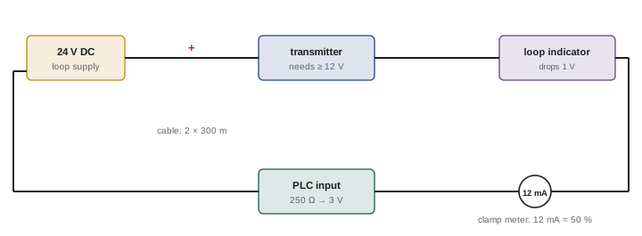
A two-wire transmitter needs at least 12 V. The loop supply is 24 V. The loop contains a 250 Ω PLC input resistor, a loop indicator dropping 1.0 V, and 300 m of cable with 13 Ω per 100 m per conductor (both conductors). Using 22 mA for the alarm current, does the loop work?
Show solution
- Maximum total resistance for the loads: (24 − 12) ÷ 0.022 = 545 Ω equivalent.
- Cable: 2 × 300 m × 0.13 Ω/m = 78 Ω.
- Indicator: 1.0 V ÷ 0.022 A ≈ 45 Ω equivalent.
- Total: 250 + 78 + 45 = 373 Ω, below 545 Ω.
- Voltage left for the transmitter at 22 mA: 24 − 0.022 × 373 = 15.8 V, above the 12 V minimum.
Answer: The loop works with margin. Adding an intrinsic safety barrier (often 250 to 350 Ω) would use up most of the remaining margin, so check again if one is added.
Temperature measurement
Two sensor types dominate industrial temperature measurement:
- Resistance temperature detectors (RTDs) use the predictable rise in resistance of platinum with temperature. A Pt100 has 100 Ω at 0 °C and rises about 0.385 Ω per °C (138.5 Ω at 100 °C). RTDs are accurate and stable, typically used from about −200 °C to 600 °C. Because the lead wires add resistance, three-wire and four-wire connections compensate for lead resistance; two-wire connections introduce errors (each ohm of lead resistance reads as about 2.6 °C).
- Thermocouples generate a small voltage (millivolts) from the junction of two dissimilar metals, proportional to the temperature difference between the measuring junction and the reference (cold) junction at the instrument. Types include J (iron-constantan), K (chromel-alumel, very common, up to about 1,250 °C), T (copper-constantan, low temperatures), and R, S and B (platinum types for very high temperatures). Thermocouples are rugged and cover high temperatures but are less accurate than RTDs. They require matching thermocouple extension wire all the way to the instrument; ordinary copper wire creates additional junctions and errors. Color codes differ between standards (North American practice under ANSI makes the negative lead red), so check carefully.
Temperature transmitters, mounted in the sensor head or on a DIN rail, convert RTD or thermocouple signals to 4–20 mA or digital signals, with linearization, cold junction compensation and sensor break detection.
Worked problem
Reading an RTD
A Pt100 RTD measures 119.25 Ω. What is the temperature, using 0.385 Ω/°C? If it were wired with two wires, each with 0.6 Ω resistance, what would the error be?
Show solution
- Temperature: (119.25 − 100) ÷ 0.385 = 19.25 ÷ 0.385 = 50 °C.
- Two-wire lead resistance: 2 × 0.6 = 1.2 Ω added.
- Error: 1.2 ÷ 0.385 ≈ 3.1 °C too high.
Answer: The temperature is 50 °C; a two-wire connection would read about 53 °C. Use three-wire or four-wire connections, or a head-mounted transmitter.
Pressure, level and flow
- Pressure transmitters use diaphragms with strain gauges, capacitive or piezoresistive sensors, measuring gauge, absolute or differential pressure. Installation details matter: impulse lines must be sloped to avoid trapped air (in liquid service) or liquid (in gas service), isolated with valve manifolds, and protected from freezing.
- Level is measured by hydrostatic pressure at the bottom of a tank (level = pressure ÷ (density × g)), differential pressure for pressurized vessels, radar and ultrasonic sensors from the top, guided wave radar along a probe, capacitance probes, and displacers or floats.
- Flow is measured by differential pressure across an orifice plate or venturi (flow is proportional to the square root of the differential pressure, so the transmitter or controller must apply square-root extraction), magnetic flowmeters for conductive liquids (no moving parts, accurate, need full pipes and proper grounding), vortex meters, ultrasonic meters, turbine meters and Coriolis meters, which measure mass flow and density directly.
HART and digital instrument communication
HART (Highway Addressable Remote Transducer) superimposes a digital signal on the 4–20 mA loop without disturbing the analog value. A handheld communicator or asset management system can read the transmitter's range, units, tag, diagnostics and secondary variables, and change its configuration remotely. HART-enabled loops need a minimum loop resistance (often 250 Ω) for the digital signal. Fully digital fieldbuses (FOUNDATION Fieldbus, PROFIBUS PA) and newer standards such as Ethernet-APL bring digital communication to field instruments, including in hazardous areas, and IO-Link serves simpler sensors (Lesson 4).
Calibration
Calibration compares an instrument's output with a known reference and adjusts it if necessary. A typical five-point calibration applies 0, 25, 50, 75 and 100 % of the input range (with a pressure calibrator, temperature bath or simulator) and records the output current at each point, rising and falling, to check zero, span, linearity and hysteresis. As-found and as-left results are documented, with the calibrator's own traceability to national standards. Loop checks during commissioning verify the whole chain: inject or simulate a value at the field device and confirm the correct reading on the PLC and HMI, including alarms and engineering units.
Intrinsic safety
In hazardous (classified) locations where flammable gases, vapors or dusts may be present, instrument loops are often intrinsically safe: energy in the circuit is limited so that sparks or hot surfaces cannot ignite the atmosphere, even under fault conditions. Zener barriers or isolating barriers in the safe area limit voltage and current; field devices must be certified intrinsically safe; and the loop's total capacitance and inductance, including the cable, must be within the barrier's entity parameters. Intrinsically safe wiring is separated from other wiring and identified (often with light blue color). The rules for hazardous locations are detailed and strictly enforced, and changes to certified loops must preserve their certification.
In the United States, hazardous locations are governed by NEC Articles 500 to 506 (division and zone systems), with intrinsically safe systems installed under Article 504 according to the certified control drawings.
Installing instrument loops
Instrument loop installation has its own good practices. Loop drawings show each instrument, junction box, terminal, cable and the PLC input, with tag numbers that match the field labels. Instrument cables are usually shielded twisted pairs, with the shield grounded at one end only (normally the control room end) to avoid ground loops, and the shield continuity maintained through junction boxes with dedicated terminals. Polarity must be observed at every terminal, since a reversed two-wire transmitter will not work. Transmitters are mounted where they can be accessed for calibration, protected from vibration and heat, and installed with isolation valves for pressure instruments.
Finally, coordinate with instrumentation technicians and process engineers: they define ranges, alarm limits and calibration intervals, and the electrician's careful installation and loop checks make sure the plant actually receives the measurements they designed.
Common mistakes
MistakeTreating 0 mA as a zero reading.
InsteadTreat currents below about 3.6 mA as a fault.
MistakeAdding loop devices without checking the resistance budget.
InsteadRecalculate voltage available at maximum current.
MistakeConnecting thermocouples with copper wire.
InsteadUse matching extension wire to the instrument.
MistakeUsing two-wire RTD connections on long runs.
InsteadUse three-wire or four-wire connections or a head transmitter.
MistakeForgetting square-root extraction on DP flow.
InsteadApply it in the transmitter or the controller, not both.
Summary and key terms
- 4–20 mA loops carry measurements as current, immune to wire resistance, with a live zero for fault detection.
- Values scale linearly from 4 mA (LRV) to 20 mA (URV).
- Two-wire transmitters are loop-powered; four-wire transmitters have separate power.
- Loop resistance budgets ensure transmitters receive their minimum voltage at maximum current.
- RTDs are accurate and need lead compensation; thermocouples cover high temperatures and need extension wire.
- Pressure, level and flow measurement each have installation requirements; DP flow needs square-root extraction.
- HART adds digital data; calibration and loop checks verify accuracy; intrinsic safety limits energy in hazardous areas.
- 4–20 mA loop
- An analog current signal representing 0 to 100 % of range.
- Live zero
- Using 4 mA rather than 0 mA as the zero point.
- LRV and URV
- Lower and upper range values of an instrument.
- Loop-powered transmitter
- A two-wire transmitter powered by its signal loop.
- Lift-off voltage
- The minimum voltage a two-wire transmitter needs.
- RTD
- Resistance temperature detector.
- Thermocouple
- A temperature sensor producing voltage from dissimilar metals.
- Cold junction compensation
- Correction for the thermocouple reference junction temperature.
- HART
- A digital protocol superimposed on 4–20 mA loops.
- Intrinsic safety
- Limiting circuit energy to prevent ignition in hazardous areas.
Practice problems
Work each problem on paper first, then reveal the answer to check.
Why is current preferred to voltage for long signal runs?
Show answer
Wire resistance does not change a series current.
What does 0 mA indicate in a 4–20 mA loop?
Show answer
A fault such as a broken wire or failed transmitter.
A 0–200 °C transmitter reads 10 mA. What is the temperature?
Show answer
(10 − 4) ÷ 16 × 200 = 75 °C.
What current represents 60 % of range?
Show answer
4 + 0.6 × 16 = 13.6 mA.
What is the maximum loop resistance for a 24 V supply, 11 V minimum and 20 mA?
Show answer
650 Ω.
What resistance does a Pt100 have at 100 °C?
Show answer
About 138.5 Ω.
Why must thermocouple extension wire match the thermocouple?
Show answer
Other metals create extra junctions and errors.
How is DP flow related to differential pressure?
Show answer
Flow is proportional to the square root of DP.
What does HART add to a 4–20 mA loop?
Show answer
Digital configuration and diagnostic data.
What does an intrinsic safety barrier do?
Show answer
Limits voltage and current into the hazardous area.
Lesson quiz · 5 questions
Score 60% or more to complete this lesson.
Create a free account to save your progress, take quizzes and earn a certificate.