
ELEC-110 · Lesson 11 of 12 · 31 min
Conductors and voltage drop
Conductors are the electrician's main material. Choosing the right size is a balance: too small and the wire overheats or delivers too little voltage to the load; too large and the job costs more than it should and the wire will not fit in boxes, conduit or terminals. This chapter explains what decides a conductor's resistance, how conductor sizes are numbered, how to calculate voltage drop on a branch circuit or feeder, and how to choose a conductor that keeps voltage drop within the code limits. Ampacity, the current a conductor can carry without overheating, is set by the code tables you will study in ELEC-120; voltage drop is the second check every electrician makes.
What decides a conductor's resistance
The resistance of a conductor depends on its material, length, cross-sectional area and temperature (Lesson 4 introduces resistivity in detail):
Here \(\rho\) is the resistivity of the material, \(L\) the length and \(A\) the cross-sectional area. In US practice, area is measured in circular mils (cmil) and resistivity is written as \(K\), in ohm-circular mils per foot: about 10.4 for copper at 20 °C (about 12.9 at 75 °C, the value the NEC voltage drop method commonly uses) and about 17 for aluminum at 20 °C. Then \(R = K\,L/\text{cmil}\), with \(L\) in feet.
- Longer conductors have proportionally more resistance.
- Larger conductors (more area) have proportionally less.
- Aluminum has about 1.64 times the resistivity of copper, so an aluminum conductor needs roughly two sizes larger to match copper.
- Resistance rises about 0.39% per °C for copper (Lesson 3). Conductors run warm under load, so calculations usually use resistance at the conductor's operating temperature, often 75 °C.
Conductor sizes
In North America, building wire up to size 4/0 is numbered in the American Wire Gauge (AWG) system. The numbering runs backwards: a smaller number means a larger wire. Every 3 gauge numbers the area doubles (and the resistance halves); every 6 gauge numbers the diameter doubles. Sizes larger than 4/0 are given by area in thousands of circular mils (kcmil): 250 kcmil, 500 kcmil and so on. A circular mil is the area of a circle 1 mil (0.001 in) across; a conductor's area in circular mils is its diameter in mils squared.
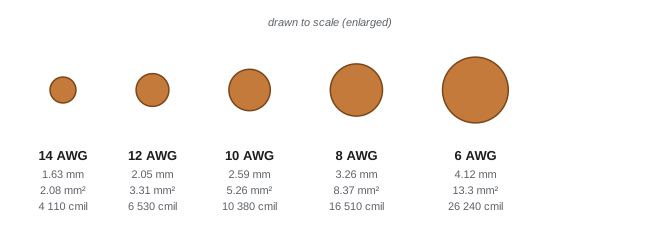
Approximate DC resistance of solid copper conductors (NEC Chapter 9, Table 8 gives exact values, including stranded conductors):
- 14 AWG: 2.525 Ω per 1000 ft at 20 °C; 3.07 Ω per 1000 ft at 75 °C.
- 12 AWG: 1.588 Ω per 1000 ft at 20 °C; 1.93 Ω per 1000 ft at 75 °C.
- 10 AWG: 0.999 Ω per 1000 ft at 20 °C; 1.22 Ω per 1000 ft at 75 °C.
- 8 AWG: 0.628 Ω per 1000 ft at 20 °C; 0.764 Ω per 1000 ft at 75 °C.
- 6 AWG: 0.395 Ω per 1000 ft at 20 °C; 0.480 Ω per 1000 ft at 75 °C.
Ampacity and voltage drop are separate checks. For small copper branch-circuit conductors, both the Canadian and US codes limit overcurrent protection to 15 A for 14 AWG, 20 A for 12 AWG and 30 A for 10 AWG in most applications, but a long run may need a larger conductor than the breaker size requires, purely to limit voltage drop.
Worked problem
Resistance of a run
Find the resistance of 100 ft of solid 12 AWG copper (6530 cmil) at 20 °C and at 75 °C.
Show solution
- At 20 °C: \(R = 10.37 \times 100/6530 = 0.159\) Ω.
- At 75 °C: \(0.159 \times [1 + 0.00393 \times 55] = 0.159 \times 1.216 = 0.193\) Ω.
Answer: About 0.16 Ω cold and 0.19 Ω warm, for one conductor. A two-wire circuit has two such conductors in its current loop
Voltage drop
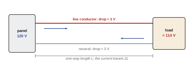
Because conductors have resistance, current through them causes a voltage drop (\(V = IR\)), so the voltage reaching the load is less than the voltage at the panel. On a two-wire circuit (single-phase, or DC), current flows out on one conductor and back on the other, so the loop length is twice the one-way distance:
where \(L\) is the one-way length and \(R\) the resistance per unit length of one conductor at operating temperature. Percentage voltage drop is \(V_d\) divided by the nominal voltage. Three-phase circuits use \(\sqrt{3}\) in place of 2 (ELEC-210).
The NEC does not make voltage drop a general requirement for branch circuits and feeders, but its informational notes recommend sizing conductors so that voltage drop is no more than 3% on a branch circuit or feeder and 5% in total from the service to the farthest outlet. Many specifications, energy codes and manufacturers' installation instructions make those limits binding, and some specific NEC articles (for example, for fire pumps and some sensitive equipment) do set enforceable limits.
Worked problem
Voltage drop on a branch circuit
A 120 V branch circuit of 12 AWG copper runs 100 ft (one way) to a 16 A load. Using 1.93 Ω per 1000 ft at 75 °C, find the voltage drop and percentage. Does it meet the 3% recommendation?
Show solution
- Loop resistance: \(2 \times 100 \times 0.00193 = 0.386\) Ω.
- \(V_d = 16 \times 0.386 = 6.18\) V.
- Percentage: \(6.18/120 = 5.2\%\). (The \(K\) method with \(K = 12.9\) gives \(2 \times 12.9 \times 16 \times 100/6530 = 6.32\) V, 5.3%, slightly higher because it assumes stranded wire.)
Answer: About 5%, well above the 3% limit for a branch circuit. The load would see about 114 V. The conductor must be upsized
Worked problem
Choosing a conductor for voltage drop
For the same 16 A load and distance, find the voltage drop with 10 AWG and with 8 AWG copper. Which size meets 3%?
Show solution
- 10 AWG: \(V_d = 16 \times 2 \times 100 \times 0.00122 = 3.89\) V = 3.2%. Not quite.
- 8 AWG: \(V_d = 16 \times 2 \times 100 \times 0.000764 = 2.44\) V = 2.0%. Meets 3%.
Answer: 8 AWG, even though 12 AWG would satisfy the 20 A breaker's ampacity requirement. In practice an electrician might instead move the panel or load closer, split the load, or, for large loads, supply it at 240 V, which halves the current and quarters the percentage drop for the same power
Worked problem
A 240 V load
A 240 V, 30 A air conditioner is 130 ft from the panel. Check 10 AWG and 8 AWG copper against 3%.
Show solution
- 10 AWG: \(V_d = 30 \times 2 \times 130 \times 0.00122 = 9.47\) V = 3.9%.
- 8 AWG: \(V_d = 30 \times 2 \times 130 \times 0.000764 = 5.96\) V = 2.5%.
Answer: 10 AWG gives about 4%, too much; 8 AWG gives about 2.5% and passes. Always check the equipment nameplate for minimum circuit ampacity and maximum overcurrent protection too
How far can a circuit run?
Rearranging the formula gives the longest one-way distance for a given current and allowed drop:
Worked problem
Maximum length for 3%
What is the longest 120 V, 12 AWG copper branch circuit that keeps voltage drop within 3% at its full 15 A load?
Show solution
- Allowed drop: 3% of 120 V = 3.6 V.
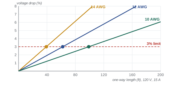
- \(L_\text{max} = 3.6/(2 \times 15 \times 0.00193) = 62\) ft.
Answer: About 62 ft at a full 15 A. Most branch circuits are not loaded to their full rating all the time, but long runs to garages, outbuildings and exterior equipment often need larger conductors
Why voltage drop matters
Low voltage at the load causes real problems:
- Resistive loads deliver less: a 1500 W heater receiving 114 V instead of 120 V produces \((114/120)^2 = 90\%\) of its rating, about 1350 W.
- Motors draw more current at low voltage to produce the same mechanical power, so they run hotter, start sluggishly and fail sooner.
- Electronic equipment may reset or malfunction; LED drivers and controls may flicker.
- The lost voltage is wasted energy: the conductors turn \(I^2R\) into heat, all day, for the life of the installation.
Voltage drop measurements are also a powerful troubleshooting tool. A large drop across a short section of conductor or a single connection, measured under load, points to a loose or corroded termination, a common cause of overheating and fires. Thermal imaging cameras find the same faults by their heat.
Aluminum conductors
Aluminum is lighter and cheaper than copper and is widely used for services, feeders and utility lines. Because its resistivity is about 1.64 times copper's, an aluminum conductor is typically two AWG sizes larger than copper for the same job. Aluminum also needs care at terminations: it oxidizes, expands and contracts more than copper, and creeps under pressure, so it must be connected only to devices and connectors marked for aluminum (such as AL/CU), with the correct torque and, where required, an anti-oxidant compound. Small-gauge aluminum branch-circuit wiring installed in some homes in the 1960s and 1970s caused many overheated connections because of these issues.
Common mistakes
MistakeUsing the one-way length in a two-wire voltage drop calculation.
InsteadCurrent flows out and back: use twice the one-way length (or √3 times the one-way length for balanced three-phase).
MistakeSizing a long run for ampacity only.
InsteadCheck voltage drop too; long runs often need a larger conductor than the breaker requires.
MistakeUsing 20 °C resistance for a loaded conductor.
InsteadUse resistance at operating temperature (often 75 °C), as the code tables do.
MistakeForgetting that a smaller AWG number means a larger wire.
Instead10 AWG is larger than 12 AWG; three gauge steps double the area.
MistakeConnecting aluminum conductors to copper-only terminals.
InsteadUse devices and connectors marked for aluminum, torque correctly, and follow the manufacturer's instructions.
Summary and key terms
- Conductor resistance \(R = KL/\text{cmil}\); copper K ≈ 10.4 at 20 °C (12.9 at 75 °C); aluminum about 1.64 times higher.
- AWG runs backwards; three gauge steps double the area. Above 4/0, sizes are in kcmil.
- Resistance rises with temperature; use operating-temperature values (often 75 °C).
- Two-wire voltage drop: \(V_d = 2IRL\) with \(L\) one way; percentage = \(V_d\)/nominal voltage.
- NEC informational notes recommend no more than 3% on a branch circuit or feeder and 5% overall; specifications and some articles make limits mandatory.
- Long runs may need larger conductors than ampacity requires; 240 V supply reduces current and percentage drop.
- Low voltage reduces heater output, overheats motors and disturbs electronics; abnormal drops at connections reveal faults.
- Aluminum needs larger sizes and terminations rated for aluminum.
- Resistivity
- A material property describing how strongly it resists current, independent of shape.
- American Wire Gauge (AWG)
- The North American system of conductor sizes, in which smaller numbers are larger wires.
- Circular mil (cmil)
- The area of a circle 1 mil (0.001 in) in diameter; conductor area in cmil equals diameter in mils squared.
- kcmil
- Thousands of circular mils, used for conductors larger than 4/0 AWG.
- Ampacity
- The current a conductor can carry continuously under its conditions of use without exceeding its temperature rating.
- Voltage drop
- The reduction in voltage along conductors caused by current flowing through their resistance.
- Feeder
- Conductors between the service equipment and the final branch-circuit overcurrent devices.
- Branch circuit
- Conductors between the final overcurrent device and the outlets or loads.
Practice problems
Work each problem on paper first, then reveal the answer to check.
How does the resistance of a conductor change if its length doubles? If its area doubles?
Show answer
Doubling length doubles resistance; doubling area halves it.
Which is larger, 8 AWG or 12 AWG? By roughly what factor does the area differ?
Show answer
8 AWG is larger; 4 gauge steps ≈ 2^(4/3) ≈ 2.5 times the area (16 510 vs 6530 cmil).
Find the voltage drop on a 120 V, 12 AWG circuit carrying 10 A over 65 ft (one way), using 1.93 Ω per 1000 ft.
Show answer
2 × 65 × 0.00193 × 10 = 2.51 V = 2.1%.
What is 3% of 240 V? Of 120 V? Of 600 V?
Show answer
7.2 V; 3.6 V; 18 V.
What is the maximum one-way length of a 120 V, 14 AWG circuit at 12 A to stay within 3%, using 3.07 Ω per 1000 ft?
Show answer
3.6/(2 × 12 × 0.00307) = 48.9 ft.
A load runs at 240 V instead of 120 V for the same power. How do its current and percentage voltage drop change on the same conductors?
Show answer
Current halves, so the voltage drop in volts halves; as a percentage of a doubled voltage it falls to one quarter.
A 2000 W heater receives 228 V instead of 240 V. What power does it produce?
Show answer
2000 × (228/240)² = 2000 × 0.9025 = 1805 W.
Under load you measure 1.8 V across a single receptacle connection. What does this suggest?
Show answer
A high-resistance (loose or corroded) connection that is heating; de-energize and repair it.
Why must aluminum conductors be about two sizes larger than copper for the same circuit?
Show answer
Aluminum's resistivity is about 1.64 times copper's; two AWG steps increase area by about 1.59 times.
A copper conductor has 0.30 Ω at 20 °C. Estimate its resistance at 75 °C.
Show answer
0.30 × 1.216 = 0.365 Ω.
Lesson quiz · 5 questions
Score 60% or more to complete this lesson.
Create a free account to save your progress, take quizzes and earn a certificate.