
ELE-470 · Lesson 9 of 12 · 30 min
Motor drives
Electric motors use roughly 40% to 45% of the world's electricity, mostly in pumps, fans, compressors and conveyors. Most of these motors are induction motors that, when connected directly to the supply, run at nearly constant speed (ELE-370). Flow and pressure are then controlled by throttling valves and dampers, wasting much of the energy. A variable-frequency drive (VFD), also called an adjustable-speed drive, combines a rectifier, a DC link and an inverter to supply the motor with variable voltage and frequency, so the motor runs at the speed the process needs. Drives save large amounts of energy, provide soft starting and precise control, and are essential in electric vehicles, elevators, robotics and data center cooling systems. This lesson ties together the previous lessons by examining drive structure, control methods, energy savings, braking, and the side effects of fast-switching inverters on motors and the electrical system.
Drive structure
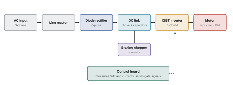
A typical low-voltage drive contains:
- A front end: usually a six-pulse diode rectifier with a DC choke or line reactor, or an active front end for regeneration and low harmonics (Lesson 3).
- A DC link: film or electrolytic capacitors that store energy and smooth the bus, with a precharge circuit that limits inrush when power is applied.
- An inverter: a three-phase IGBT (or increasingly SiC) bridge using space vector PWM at 2 kHz to 16 kHz (Lesson 7).
- Control: a microprocessor that measures currents and voltage, runs the motor control algorithm and protection, and communicates with building or process systems.
- Optional components: a braking chopper and resistor, input and output filters, and safety functions.
Speed control of induction motors
An induction motor's synchronous speed is set by the supply frequency and the number of poles:
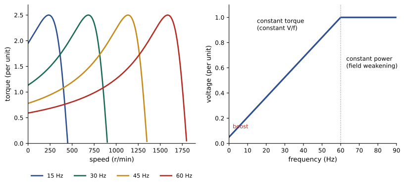
and the rotor runs slightly slower, at slip \(s = (n_s - n)/n_s\), typically 1% to 4% at full load. Changing the frequency changes the speed. To keep the magnetic flux, and therefore the torque capability, constant, the voltage must change in proportion to frequency, because the air-gap flux is proportional to \(V/f\). This is constant volts-per-hertz (V/f) control, the simplest drive control method:
At low speeds, the voltage drop across the stator resistance becomes significant, so drives add a voltage boost to maintain torque. Above rated frequency, the voltage cannot rise further (the DC bus limits it), so the flux weakens: the motor can run faster but with torque falling roughly in inverse proportion to speed, giving constant power operation.
Worked problem
Volts per hertz
A 460 V, 60 Hz, 4-pole motor with 2.5% rated slip is run at 40 Hz with constant V/f. What voltage does the drive apply, and what is the approximate speed if the slip speed in r/min stays the same?
Show solution
- Voltage: \(460 \times 40/60 = 307\) V.
- Synchronous speeds: 1800 r/min at 60 Hz and 1200 r/min at 40 Hz. Rated slip speed: \(0.025 \times 1800 = 45\) r/min.
- Speed at 40 Hz and the same torque: \(1200 - 45 = 1155\) r/min.
Answer: About 307 V and 1155 r/min. With constant flux, the motor's torque-speed curve shifts left with frequency while keeping its shape, so the slip speed for a given torque stays roughly constant.
Vector control
V/f control is adequate for fans and pumps but responds slowly and cannot give full torque at zero speed. Field-oriented control (FOC), or vector control, transforms the three motor currents into a rotating reference frame aligned with the rotor flux, splitting them into a flux-producing component \(i_d\) and a torque-producing component \(i_q\). Controlling these separately makes an AC motor behave like a separately excited DC motor, with fast, precise torque control:
Vector control can use a speed encoder (closed loop) or estimate speed from currents and voltages (sensorless). Direct torque control (DTC) is an alternative that selects inverter states directly from torque and flux errors. Permanent magnet synchronous motors, used in electric vehicles, high-efficiency pumps and compressors, and some data center fans, always require vector-type control; they offer higher efficiency and power density than induction motors because the rotor has no current-carrying conductors.
Energy savings with fans and pumps
The largest energy savings from drives come in centrifugal fans and pumps, which follow the affinity laws: flow is proportional to speed, pressure to speed squared, and power to speed cubed:
Reducing speed to 80% cuts the ideal power to about 51%. By contrast, throttling a fixed-speed fan with a damper or a pump with a valve reduces flow while power falls only a little. In practice, systems with significant static pressure (for example, pumps lifting water to a height, or systems with fixed pressure setpoints) save less than the cube law predicts, so savings should be estimated from the actual system curve.
P_rated = 75.0
hours = {100: 1500, 80: 3000, 60: 3000, 40: 1260}
price = 0.12
eff_drive = 0.97


def damper_kw(flow):
    return P_rated * (0.55 + 0.45 * flow / 100)


def vfd_kw(flow):
    return P_rated * (flow / 100) ** 3 / eff_drive


e_damper = sum(damper_kw(q) * h for q, h in hours.items())
e_vfd = sum(vfd_kw(q) * h for q, h in hours.items())
for q in hours:
    print(f"flow {q:>3}%: damper {damper_kw(q):5.1f} kW   VFD {vfd_kw(q):5.1f} kW   speed {q}%  ({hours[q]} h/yr)")
print(f"annual energy: damper {e_damper / 1000:.0f} MWh, VFD {e_vfd / 1000:.0f} MWh, saving {(e_damper - e_vfd) / 1000:.0f} MWh = ${(e_damper - e_vfd) * price:,.0f} per year at ${price}/kWh")flow 100%: damper 75.0 kW VFD 77.3 kW speed 100% (1500 h/yr) flow 80%: damper 68.2 kW VFD 39.6 kW speed 80% (3000 h/yr) flow 60%: damper 61.5 kW VFD 16.7 kW speed 60% (3000 h/yr) flow 40%: damper 54.8 kW VFD 4.9 kW speed 40% (1260 h/yr) annual energy: damper 571 MWh, VFD 291 MWh, saving 280 MWh = $33,559 per year at $0.12/kWh
At full flow the drive costs a little energy (its own losses), but over a year of part-load operation it roughly halves consumption. Data center cooling systems rely heavily on drives: computer room air handlers, chilled water pumps, chiller compressors and cooling tower fans all modulate speed to match the IT load, which is a major reason for improvements in power usage effectiveness (DCE-330).
Braking and regeneration
When a drive slows a motor quickly, or when the load drives the motor (a lowering hoist, a downhill vehicle, an overhauling conveyor), the motor acts as a generator and returns energy to the DC link. With a diode front end, this energy cannot flow back to the supply and raises the DC bus voltage, so the drive must limit deceleration or dissipate the energy:
- A braking chopper switches a resistor across the DC bus when the voltage exceeds a threshold, converting the energy to heat (dynamic braking).
- An active front end or regenerative unit returns the energy to the grid, which pays off in elevators, cranes, test stands and centrifuges.
- A common DC bus lets one drive's braking energy power others.
Worked problem
Braking resistor energy
A centrifuge with a moment of inertia of 25 kg·m² is braked from 3000 r/min to rest in 20 s. How much energy must the braking resistor absorb and what is the average power (ignoring losses)?
Show solution
- Angular speed: \(\omega = 3000 \times 2\pi/60 = 314\) rad/s.
- Kinetic energy: \(E = \tfrac{1}{2} J \omega^2 = 0.5 \times 25 \times 314^2 = 1.23\) MJ.
- Average power: \(1.23 \times 10^6 / 20 = 61.7\) kW.
Answer: About 1.23 MJ at an average of 62 kW (peak about 123 kW at the start of a constant-torque stop). If the centrifuge stops many times an hour, a regenerative front end could return most of this energy instead of wasting it.
Side effects of PWM drives on motors
The fast voltage edges of PWM inverters, with rise times of 50 ns to a few hundred nanoseconds, create problems that do not occur with sinusoidal supplies:
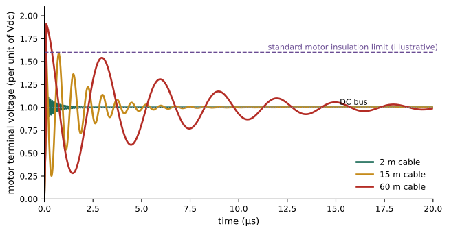
- Reflected wave overvoltage: the motor cable behaves as a transmission line. Because the motor's surge impedance is much higher than the cable's, a voltage edge reflects at the motor terminals and can nearly double the voltage if the cable is longer than a critical length related to the rise time. Peaks of 1,300 V to 1,600 V on a 480 V or 600 V system can break down motor winding insulation over time.
- Uneven voltage distribution: the first turns of a winding see most of a fast edge, stressing turn-to-turn insulation.
- Common-mode voltage and bearing currents: the inverter's output phases do not sum to zero, producing a common-mode voltage that couples through stray capacitances to the rotor and discharges through the bearings, causing electrical discharge machining that pits races (fluting) and leads to bearing failure.
- Electromagnetic interference from high-frequency currents in cables and ground paths.
where \(l_c\) is the critical cable length, \(v\) the propagation velocity in the cable (roughly 150 to 200 m/µs), and \(t_r\) the voltage rise time.
Worked problem
Critical cable length
Estimate the critical cable length for an IGBT drive with a rise time of 100 ns and a SiC drive with a rise time of 30 ns, taking \(v = 160\) m/µs.
Show solution
- IGBT: \(l_c = 160 \times 0.1/2 = 8\) m.
- SiC: \(l_c = 160 \times 0.03/2 = 2.4\) m.
Answer: About 8 m for the IGBT drive and only 2.4 m for SiC, so almost any practical installation exceeds the critical length and sees significant reflected-wave overvoltage. Remedies include inverter-duty motors with reinforced insulation, output reactors, dv/dt filters or sine-wave filters at the drive, and keeping cables short. Bearing current remedies include shaft grounding rings, insulated or ceramic bearings, symmetrical shielded motor cables with proper bonding, and common-mode filters.
Motors intended for drive operation should meet inverter-duty insulation requirements, commonly specified using NEMA MG 1 Part 31 (for example, withstanding peaks of 3.1 times rated voltage for motors up to 600 V), and drives are listed to UL 61800-5-1. Installation follows NEC Article 430 Part X for adjustable-speed drive systems, which sizes conductors at 125% of the drive's rated input current (430.122).
Drives and the electrical system
Drives affect the supply as well as the motor. Their rectifiers draw harmonic currents (Lesson 3); the precharge and DC link make their input power factor near unity in displacement but distorted; and they can trip on voltage sags because the DC bus discharges quickly. Ride-through features keep drives running through short sags by using the load's kinetic energy to hold up the DC bus, which is important in data centers where cooling must restart quickly after a transfer to generators. Drives also provide soft starting, eliminating the large inrush of direct-on-line starting, which reduces the generator capacity needed (ELEC-220).
Modern drives include safety functions such as Safe Torque Off (STO), which removes the gate signals through a certified safety channel so the motor cannot produce torque, allowing safe maintenance of machinery without removing all power, defined in IEC 61800-5-2. Drives also report energy, faults and condition data through industrial and building networks.
Applications
Beyond fans and pumps, drives power electric and hybrid vehicles (with SiC traction inverters at 400 V to 800 V), electric trains, ship propulsion, wind turbines (full or partial converters), compressors in chillers and heat pumps, conveyors, cranes, elevators, machine tools and robots. Medium-voltage drives (2.3 kV to 13.8 kV) using multilevel inverters control large pumps, compressors and mills of several megawatts. In each, the same building blocks appear: a front end, a DC link, an inverter, and a control algorithm.
Lesson 8 explains the electromagnetic interference and layout principles behind several of the side effects described here, and Lesson 12 offers a drive design as one of the course project options.
Common mistakes
MistakeAssuming cube-law savings in systems with high static pressure.
InsteadEstimate savings from the actual system curve.
MistakeRunning a standard motor on a long cable from a fast drive.
InsteadUse inverter-duty motors and dv/dt or sine filters.
MistakeIgnoring bearing currents.
InsteadUse shaft grounding, insulated bearings and proper cable bonding.
MistakeDecelerating high-inertia loads quickly without braking provision.
InsteadAdd a braking resistor or regenerative front end.
MistakeRelying on drive enable signals for maintenance safety.
InsteadUse certified Safe Torque Off with proper lockout procedures.
Summary and key terms
- A VFD combines a rectifier, DC link and PWM inverter to vary motor voltage and frequency.
- Constant V/f keeps flux constant below rated speed; above it, field weakening gives constant power.
- Field-oriented control splits current into flux and torque components for fast, precise control.
- Affinity laws make fan and pump power fall with the cube of speed; savings can halve energy use.
- Regenerated energy is dissipated in braking resistors or returned by active front ends.
- Fast PWM edges cause reflected-wave overvoltage, insulation stress and bearing currents.
- Drives need harmonic management, ride-through, safety functions and code-compliant installation.
- Variable-frequency drive
- A converter supplying a motor with variable voltage and frequency.
- V/f control
- Varying voltage in proportion to frequency to keep flux constant.
- Field weakening
- Operation above rated speed with reduced flux and constant power.
- Field-oriented control
- Control of flux and torque current components in a rotating frame.
- Affinity laws
- Relations of flow, pressure and power to speed for centrifugal machines.
- Dynamic braking
- Dissipating regenerated energy in a resistor.
- Reflected wave
- Overvoltage at a motor caused by transmission-line effects in the cable.
- Critical cable length
- The length beyond which reflected-wave overvoltage becomes severe.
- Bearing currents
- Currents through motor bearings driven by common-mode voltage.
- Safe Torque Off
- A certified function preventing a drive from producing torque.
Practice problems
Work each problem on paper first, then reveal the answer to check.
Synchronous speed of a 6-pole motor at 50 Hz?
Show answer
1000 r/min.
460 V, 60 Hz motor at 30 Hz with constant V/f. Voltage?
Show answer
230 V.
Why add voltage boost at low frequency?
Show answer
To compensate for stator resistance drop and maintain torque.
What happens to torque capability above rated frequency?
Show answer
It falls roughly inversely with speed (constant power).
Fan power at 70% speed (ideal)?
Show answer
0.343 of full-speed power.
Pump at 90% speed. Head?
Show answer
81% of full-speed head.
J = 10 kg·m² braked from 1800 r/min. Energy?
Show answer
ω = 188.5 rad/s; E = 0.5 × 10 × 188.5² = 178 kJ.
Rise time 200 ns, v = 150 m/µs. Critical cable length?
Show answer
15 m.
Name two remedies for bearing currents.
Show answer
Shaft grounding rings, insulated bearings, shielded symmetrical cable, common-mode filters.
What does Safe Torque Off do?
Show answer
Removes gate signals so the motor cannot produce torque, through a certified safety channel.
Lesson quiz · 5 questions
Score 60% or more to complete this lesson.
Create a free account to save your progress, take quizzes and earn a certificate.