
ELE-470 · Lesson 5 of 12 · 32 min
DC-DC converters
DC-DC converters change one DC voltage into another: stepping down 48 V to 12 V or 12 V to the 0.7 V to 1 V needed by processor cores, stepping up a battery's voltage to a DC bus, or providing isolation between circuits. They are the most numerous power converters in existence: a single AI server contains dozens, delivering hundreds of amperes to each accelerator chip. This lesson derives the three basic non-isolated converters (buck, boost and buck-boost) from the principles of inductor volt-second balance and capacitor charge balance, shows how to size their inductors and capacitors, introduces the isolated converters used when a transformer is needed, and describes how power is delivered inside a modern data center rack.
Two key principles
In steady state, the current in an inductor returns to the same value at the end of each switching period, so the average voltage across it over a period must be zero (volt-second balance):
Similarly, the voltage on a capacitor returns to the same value, so the average current into it is zero (charge balance). These two principles give the steady-state voltage ratio of any converter quickly. The inductor current ripple follows from \(v = L\, di/dt\) during each interval, and the capacitor voltage ripple from the charge that flows in and out.
The buck converter
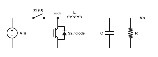
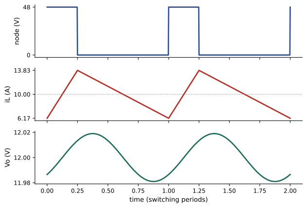
A buck (step-down) converter has a switch from the input to a node, a diode or second switch from that node to ground, an inductor from the node to the output, and an output capacitor. With the switch on for a fraction \(D\) of each period, the node voltage is \(V_{in}\); with it off, the node is at ground (the diode or lower switch carries the inductor current). Volt-second balance on the inductor gives:
The inductor current ripple and output voltage ripple in continuous conduction are:
import numpy as np

Vin, Vo_target, R = 48.0, 12.0, 1.2
L, C, fs = 4.7e-6, 100e-6, 250e3
D = Vo_target / Vin
dt = 1 / fs / 400
steps = int(3e-3 / dt)
iL, vC = 0.0, 0.0
log_i, log_v = [], []
for k in range(steps):
    on = (k % 400) < D * 400
    vx = Vin if on else 0.0
    if not on and iL <= 0:
        vx, iL = vC, 0.0
    iL += (vx - vC) / L * dt
    vC += (iL - vC / R) / C * dt
    log_i.append(iL)
    log_v.append(vC)
n = 4 * 400
i_ss, v_ss = np.array(log_i[-n:]), np.array(log_v[-n:])
print(f"duty cycle D = {D:.2f}")
print(f"simulated: Vo = {v_ss.mean():.2f} V, ripple {1000 * np.ptp(v_ss):.0f} mV p-p; IL = {i_ss.mean():.2f} A, ripple {np.ptp(i_ss):.2f} A p-p")
dI = (Vin - Vo_target) * D / (L * fs)
dV = dI / (8 * fs * C)
print(f"formulas:  dIL = (Vin - Vo) D / (L fs) = {dI:.2f} A,  dVo = dIL / (8 fs C) = {1000 * dV:.0f} mV")
print(f"boundary of continuous conduction at load current {dI / 2:.2f} A")duty cycle D = 0.25 simulated: Vo = 12.00 V, ripple 38 mV p-p; IL = 10.00 A, ripple 7.66 A p-p formulas: dIL = (Vin - Vo) D / (L fs) = 7.66 A, dVo = dIL / (8 fs C) = 38 mV boundary of continuous conduction at load current 3.83 A
The simulated ripple matches the formulas once the converter reaches steady state. If the load current falls below half the ripple (3.83 A in this design), the inductor current would reach zero during the off time with a diode, and the converter enters discontinuous conduction mode (DCM), where the simple voltage ratio no longer holds. Synchronous converters, which use a MOSFET instead of the diode, can keep conducting with negative current, but at the cost of circulating losses at light load, so many controllers switch to pulse skipping at light load.
Worked problem
Designing a buck converter
Design a buck converter from 12 V to 1.0 V at 30 A, switching at 500 kHz, with inductor ripple of 30% of load current and output ripple below 10 mV.
Show solution
- Duty cycle: \(D = 1/12 = 0.083\).
- Ripple current: \(0.3 \times 30 = 9\) A. Inductance: \(L = (12 - 1)(0.083)/(9 \times 5 \times 10^{5}) = 0.20\) µH.
- Capacitance: \(C \ge 9/(8 \times 5 \times 10^{5} \times 0.01) = 225\) µF (plus allowance for capacitor ESR).
Answer: About 0.2 µH and at least 225 µF of low-ESR ceramic capacitance. The very small duty cycle (on time of only 167 ns) is one reason why processor power is delivered in two stages, 48 V to 12 V or lower and then to 1 V, or with special topologies.
The boost converter
A boost (step-up) converter places the inductor at the input, a switch from the inductor's end to ground, and a diode to the output capacitor. When the switch is on, the inductor charges from the input; when it turns off, the inductor's voltage adds to the input to push current into the output. Volt-second balance gives:
Boost converters are used in power factor correction stages (Lesson 3), solar optimizers, battery-powered devices and LED drivers. Their output capacitor receives pulsed current, so output ripple is larger than in a buck for the same capacitance, and the gain is limited in practice to about 4 to 6 by losses in the inductor and switch, which grow as \(D\) approaches 1.
Worked problem
Boost duty cycle and currents
A PFC boost stage must produce 400 V from an instantaneous rectified input of 120 V while delivering 1,000 W. What duty cycle is needed at that instant, and what is the inductor current (ignoring losses)?
Show solution
- \(D = 1 - V_{in}/V_o = 1 - 120/400 = 0.70\).
- Instantaneous input power equals output power: \(I_L = 1000/120 = 8.3\) A.
Answer: A duty cycle of 0.70 and about 8.3 A at that point of the cycle. In a PFC stage, the controller varies D continuously through each half-cycle so that the inductor current follows a sinusoid proportional to the input voltage.
Buck-boost and other non-isolated converters
A buck-boost converter can produce an output larger or smaller than the input, with inverted polarity in its basic form:
Variants such as the SEPIC and Ćuk converters give non-inverted or inverted outputs with continuous input current, and the four-switch buck-boost combines a buck and a boost stage to handle inputs above and below the output, as in USB-C chargers and battery systems. Multiphase interleaved converters place several buck stages in parallel, switching at equally spaced times, so their ripples partly cancel: processor voltage regulators commonly use 8 to over 20 phases to deliver hundreds of amperes with fast transient response.
| Converter | Voltage ratio (CCM) | Typical uses |
|---|---|---|
| Buck | \(D\) | Point-of-load regulators, 48 V to 12 V, battery chargers |
| Boost | \(1/(1 - D)\) | PFC, solar, battery to DC bus |
| Buck-boost | \(-D/(1 - D)\) | Wide-range inputs, negative rails |
| Four-switch buck-boost | \(D_1/(1 - D_2)\) | USB-C power, battery systems |
Isolated converters
Many applications require galvanic isolation (for safety, to separate grounds, or to allow large voltage ratios) and use a high-frequency transformer. Because transformer size falls with frequency, a transformer operating at 100 kHz is far smaller than a 60 Hz transformer of the same power.
- Flyback: a buck-boost with a coupled inductor; energy is stored in the core while the switch is on and released to the output when it turns off. Simple and cheap, used up to about 100 W to 150 W in chargers, adapters and auxiliary supplies.
- Forward: a buck with a transformer; energy is transferred while the switch is on, needing a way to reset the core. Used from tens to hundreds of watts.
- Half-bridge and full-bridge (phase-shifted) converters: for hundreds of watts to tens of kilowatts.
- LLC resonant converters: a resonant tank of inductors and a capacitor allows switches to turn on at zero voltage (soft switching), greatly reducing switching loss and allowing high frequencies and efficiencies near 98%. Widely used in server power supplies after the PFC stage.
- Dual active bridge (DAB): two full bridges linked by a transformer, controlling power flow in either direction by the phase shift between them; used in solid-state transformers, EV chargers and battery systems.
Worked problem
Flyback turns ratio
A flyback adapter converts a 340 V DC bus (rectified 240 V) to 20 V. The design uses a maximum duty cycle of 0.45. What turns ratio \(N_p/N_s\) is needed?
Show solution
- From \(V_o = (N_s/N_p)\, \frac{D}{1-D} V_{in}\): \(N_s/N_p = \frac{V_o (1-D)}{D\, V_{in}} = \frac{20 \times 0.55}{0.45 \times 340} = 0.0719\).
- \(N_p/N_s = 13.9\).
Answer: A turns ratio of about 14:1. The switch must then withstand \(V_{in} + (N_p/N_s) V_o = 340 + 278 = 618\) V plus leakage-inductance spikes, so an 800 V or higher rated device and a clamp circuit are needed.
Control
DC-DC converters regulate their output with feedback. In voltage-mode control, an error amplifier compares the output with a reference and adjusts the duty cycle through a pulse-width modulator. Peak current-mode control adds an inner loop that turns the switch off when the inductor current reaches a level set by the voltage loop, giving inherent current limiting and simpler compensation. Designers check stability with loop gain and phase margin (ELE-390). Digital controllers implement these loops in microcontrollers or dedicated chips, report telemetry such as voltage, current and temperature over the PMBus interface, and allow voltages to be adjusted dynamically, which processors use to save energy.
Efficiency and losses
Converter losses come from three groups with different dependence on load: fixed losses (gate drive, control circuits, core losses, switching losses at constant voltage) that are present even at no load; losses proportional to current (diode and IGBT drops); and losses proportional to current squared (resistance in switches, windings and traces). Efficiency is therefore low at light load, peaks at an intermediate load where fixed losses equal the \(I^2R\) losses, and falls slightly at full load.
P_rated = 3000.0
fixed, prop, quad = 18.0, 0.012, 1.4e-5
titanium = {10: 90, 20: 94, 50: 96, 100: 91}
print("load   output W   losses W   efficiency   Titanium minimum")
for pct in [5, 10, 20, 50, 75, 100]:
    P = P_rated * pct / 100
    loss = fixed + prop * P + quad * P ** 2
    eff = 100 * P / (P + loss)
    req = titanium.get(pct)
    note = f"{req}% {chr(10003) if req and eff >= req else (chr(10007) if req else chr(32))}" if req else ""
    print(f"{pct:>3}%   {P:8.0f}   {loss:8.1f}   {eff:9.2f}%   {note}")
best = max(range(1, 101), key=lambda p: (P_rated * p / 100) / (P_rated * p / 100 + fixed + prop * P_rated * p / 100 + quad * (P_rated * p / 100) ** 2))
print(f"peak efficiency near {best}% load, where fixed losses equal load-squared losses")load output W losses W efficiency Titanium minimum 5% 150 20.1 88.18% 10% 300 22.9 92.92% 90% ✓ 20% 600 30.2 95.20% 94% ✓ 50% 1500 67.5 95.69% 96% ✗ 75% 2250 115.9 95.10% 100% 3000 180.0 94.34% 91% ✓ peak efficiency near 38% load, where fixed losses equal load-squared losses
This matters in data centers, where redundant power supplies often share load and therefore operate at 20% to 40% of rating. Efficiency certifications such as 80 PLUS Titanium specify minimum efficiency at 10%, 20%, 50% and 100% load. In the model, the supply misses the 50% requirement, so the designer would reduce resistance (larger conductors, lower on-resistance devices) or core losses.
Power delivery in a data center rack
The power path inside a modern AI or cloud rack shows how many converters work in series:
1. AC (often 415/240 V or 480/277 V three-phase in North America) enters rack power shelves.
2. Power supply units with PFC and LLC stages convert it to a DC bus, increasingly about 48 V to 54 V (the Open Compute Project standard) instead of 12 V, which cuts bus current and distribution losses by a factor of 16 for the same power.
3. On each board, intermediate bus converters (often fixed-ratio, highly efficient) step 48 V down to 12 V or lower.
4. Multiphase voltage regulators step down to about 0.7 V to 1 V at hundreds to over a thousand amperes for each processor or accelerator, often mounted directly beneath the chip (vertical power delivery) to minimize resistance.
Because rack power has grown from about 10 kW to over 100 kW for AI clusters, the industry has begun developing higher-voltage DC distribution (for example ±400 V or 800 V DC to the rack) to reduce copper and conversion stages. Each conversion stage costs 1% to 5%, so the end-to-end efficiency from the utility to the chip is the product of many efficiencies.
Worked problem
End-to-end efficiency
A power chain has a UPS at 97%, a PSU at 96%, an intermediate bus converter at 97.5% and a processor voltage regulator at 90%. What fraction of utility power reaches the processor, and how much is lost for a 100 kW rack?
Show solution
- Product: \(0.97 \times 0.96 \times 0.975 \times 0.90 = 0.817\).
- Input for 100 kW at the chips: \(100/0.817 = 122.4\) kW; losses 22.4 kW.
Answer: About 82% reaches the processors; over 22 kW per rack is lost as heat that the cooling system must also remove. Improving the last stage, where currents are highest, gives the biggest gain.

Lesson 6 develops the averaged models and compensator design behind the control methods outlined here, and Lesson 12 applies these converters in a complete power supply design.
Common mistakes
MistakeUsing V_o = D·V_in for a buck in discontinuous conduction.
InsteadCheck that load current exceeds half the inductor ripple.
MistakePushing a boost converter to very high gain.
InsteadLosses grow as D approaches 1; use isolated topologies for large ratios.
MistakeSizing output capacitors from capacitance alone.
InsteadInclude ESR, ripple current rating and capacitance loss with DC bias.
MistakeIgnoring light-load efficiency in redundant supplies.
InsteadDesign for efficiency at 20% to 50% load.
MistakeForgetting switch voltage stress in a flyback.
InsteadAdd the reflected output voltage and leakage spikes to the input.
Summary and key terms
- Volt-second balance and charge balance give steady-state converter equations.
- Buck: V_o = D·V_in; ripple ΔI = (V_in − V_o)D/(L f_s), ΔV ≈ ΔI/(8 f_s C).
- Boost: V_o = V_in/(1 − D); buck-boost: −D/(1 − D).
- Below half the ripple current, converters enter discontinuous conduction.
- Isolated converters (flyback, forward, bridge, LLC, DAB) use high-frequency transformers.
- Current-mode control, digital controllers and PMBus telemetry are standard.
- Efficiency peaks at intermediate load; data centers need high efficiency at partial load.
- Rack power moves from AC through 48 V buses to sub-1 V regulators; each stage costs efficiency.
- Volt-second balance
- Zero average inductor voltage over a period in steady state.
- Charge balance
- Zero average capacitor current over a period in steady state.
- Buck converter
- A step-down DC-DC converter.
- Boost converter
- A step-up DC-DC converter.
- Continuous conduction mode
- Operation where inductor current never reaches zero.
- Synchronous rectification
- Using a MOSFET instead of a diode to reduce losses.
- Interleaving
- Paralleling phases switched at staggered times to cancel ripple.
- Flyback converter
- An isolated buck-boost using a coupled inductor.
- LLC converter
- A resonant converter achieving soft switching.
- Intermediate bus converter
- A converter stepping a distribution bus down to a board-level bus.
Practice problems
Work each problem on paper first, then reveal the answer to check.
Buck from 24 V to 5 V. Duty cycle?
Show answer
0.208.
Buck 24 V to 5 V, L = 10 µH, f = 300 kHz. Inductor ripple?
Show answer
19 × 0.208/(10e-6 × 3e5) = 1.32 A.
Ripple 2 A, f = 200 kHz, C = 47 µF. Output ripple?
Show answer
2/(8 × 2e5 × 47e-6) = 26.6 mV.
Boost from 12 V to 48 V. Duty cycle?
Show answer
0.75.
Buck-boost with D = 0.6 from 12 V. Output?
Show answer
−18 V.
When does a diode buck enter DCM?
Show answer
When load current falls below half the inductor ripple current.
Forward converter, Ns/Np = 0.1, D = 0.4, 300 V input. Output?
Show answer
12 V.
Why does 48 V distribution reduce losses compared with 12 V?
Show answer
Current falls by 4, so I²R losses fall by 16.
Fixed losses 10 W, I²R losses 40 W at full load. Where is peak efficiency?
Show answer
Where I²R = 10 W: at 50% load.
Stages at 98%, 97% and 92%. Overall efficiency?
Show answer
0.875, about 87.5%.
Lesson quiz · 5 questions
Score 60% or more to complete this lesson.
Create a free account to save your progress, take quizzes and earn a certificate.