
ELE-240 · Lesson 7 of 12 · 25 min
BJT DC biasing and the transistor switch
Before a transistor can amplify, it must be biased: given steady DC currents and voltages that place its operating point where the signal can swing without running into cutoff or saturation. Before it can switch, it must be driven hard enough to saturate under every condition. Both jobs come down to the same skill, DC analysis of transistor circuits, and both share the same enemy, the wide spread and temperature drift of β and v_BE. This lesson shows how to analyze any BJT circuit at DC, why some bias circuits are good and others are not, and how to design a transistor switch and a constant-current source.
Three pieces of Cedarline hardware depend on it: the bias network for the microphone amplifier's input transistor, the constant-current sinks that drive the LED strings in the walk symbol, and the transistor that switches the coil of the flash transfer relay, which drops the intersection to flashing red if the conflict monitor detects a fault.
A procedure for DC analysis
DC analysis of a BJT circuit follows the same assume-and-check method used for diodes. Set all AC signal sources to zero and treat capacitors as open circuits. Assume the transistor is active, so V_BE ≈ 0.7 V (or V_EB ≈ 0.7 V for pnp) and I_C = βI_B. Write Kirchhoff's laws around the base–emitter loop to find the base or emitter current, then find the collector current and the collector voltage. Finally check that V_CE is greater than about 0.3 V, confirming active mode. If it is not, the transistor is saturated: replace the assumption with V_CE = V_CE(sat) ≈ 0.2 V and solve again, this time without using I_C = βI_B.
Why fixed base bias fails
The most obvious bias circuit connects a single resistor R_B from the supply to the base. The base current is (V_CC − 0.7)/R_B, nearly constant, and the collector current is β times that. The trouble is that β is not constant. If a design gives I_C = 2 mA with β = 100, a part with β = 300 runs at 6 mA, and the collector voltage, which was meant to sit in the middle of the supply, collapses into saturation. Fixed bias also gets worse as the transistor warms, because β rises and v_BE falls. It is a textbook example of what not to do, useful only to show why the better circuits are built the way they are.
The voltage-divider bias circuit
The standard discrete bias network, sometimes called four-resistor bias, uses a divider R_1 and R_2 to hold the base near a fixed voltage, and an emitter resistor R_E. The emitter sits one V_BE below the base, so the emitter current is set by the base voltage and R_E, almost independent of β. If the collector current tries to rise, the voltage across R_E rises, the base–emitter voltage falls, and the current is pulled back. This is negative feedback, called emitter degeneration, and it is the key to stable bias.
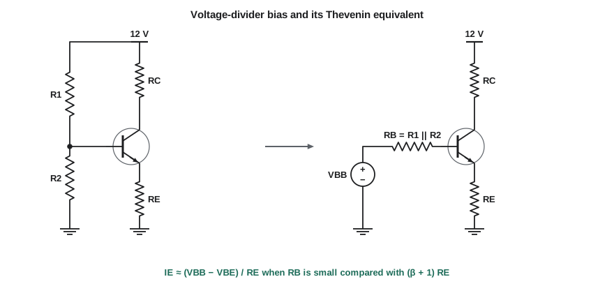
To analyze it, replace the divider with its Thévenin equivalent, V_BB = V_CC R_2/(R_1 + R_2) in series with R_B = R_1 ∥ R_2. The base–emitter loop then gives
If R_E is much larger than R_B/(β + 1), the β term vanishes and I_E ≈ (V_BB − V_BE)/R_E. The usual design rule is to make the current in the divider about ten times the base current, which is equivalent to R_B ≤ (β_min + 1)R_E / 10. Larger divider currents give better stability but waste power and load the signal source more heavily, so the rule is a compromise. A second rule is to make V_E, the voltage across R_E, at least 1 to 2 V, so that the 2 mV/°C drift of V_BE and part-to-part spread in V_BE are small compared with it.
Worked problem
Biasing the microphone amplifier input stage
Design a voltage-divider bias for I_C = 1 mA from V_CC = 12 V, with V_E ≈ 1.5 V and the collector at about 7 V, for β between 100 and 300. Then find I_C at both extremes of β.
Show solution
- \[R_E = \frac{1.5}{1\ \text{mA}} = 1.5\ \text{k}\Omega, \qquad R_C = \frac{12 - 7}{1\ \text{mA}} = 5\ \text{k}\Omega \to 5.1\ \text{k}\Omega\]
- \[V_B = 1.5 + 0.7 = 2.2\ \text{V}; \quad R_B \le \frac{101 \times 1500}{10} \approx 15\ \text{k}\Omega\]
- Choose R_2 = 18 kΩ and R_1 = 82 kΩ: V_BB = 12 × 18/100 = 2.16 V and R_B = 18 ∥ 82 ≈ 14.8 kΩ.
- \[I_E(\beta=100) = \frac{2.16 - 0.7}{1500 + 14\,800/101} = \frac{1.46}{1647} \approx 0.887\ \text{mA}\]
- \[I_E(\beta=300) = \frac{1.46}{1500 + 14\,800/301} = \frac{1.46}{1549} \approx 0.943\ \text{mA}\]
Answer: Tripling β changes the collector current by only about 6 percent, from 0.88 to 0.94 mA, and the collector voltage stays near 7.3 to 7.5 V. Fixed bias would have tripled the current. Daniel accepts the slightly low current, or trims R_2 to 20 kΩ to center it near 1 mA.
# Voltage-divider bias: Q-point across beta and temperature
VCC, R1, R2, RC, RE = 12.0, 82e3, 18e3, 5.1e3, 1.5e3
VBB, RB = VCC * R2 / (R1 + R2), R1 * R2 / (R1 + R2)
for temp, vbe in ((-40, 0.83), (25, 0.70), (74, 0.60)):
    for beta in (100, 300):
        IE = (VBB - vbe) / (RE + RB / (beta + 1))
        IC = IE * beta / (beta + 1)
        VCE = VCC - IC * RC - IE * RE
        mode = "active" if VCE > 0.3 else "saturated"
print(f"{temp:4d} C beta={beta}: IC = {IC*1000:.3f} mA, VCE = {VCE:.2f} V ({mode})")-40 C beta=100: IC = 0.800 mA, VCE = 6.71 V (active) -40 C beta=300: IC = 0.856 mA, VCE = 6.35 V (active) 25 C beta=100: IC = 0.878 mA, VCE = 6.19 V (active) 25 C beta=300: IC = 0.939 mA, VCE = 5.80 V (active) 74 C beta=100: IC = 0.938 mA, VCE = 5.79 V (active) 74 C beta=300: IC = 1.004 mA, VCE = 5.37 V (active)
The program reveals something the hand calculation hid. Across the full temperature range the bias current moves by roughly 25 percent, mostly because V_BE changes by about 0.23 V while V_E is only about 1.4 V. A larger V_E would reduce this, at the cost of collector swing. Every bias design is a trade-off between stability, swing and power.
Other bias arrangements
Collector feedback bias connects the base resistor to the collector instead of the supply. If the collector current rises, the collector voltage falls and reduces the base current, another form of negative feedback, with only two resistors. Dual-supply bias, common in op amp-like designs, grounds the base through a resistor and returns the emitter resistor to a negative supply, so I_E ≈ (V_EE − 0.7)/R_E is set almost entirely by the negative supply. In integrated circuits, where large resistors and capacitors are expensive, transistors are biased by current mirrors, described below.
Constant-current sources and sinks
A transistor with a fixed base voltage and an emitter resistor is also an excellent current source, because the collector current is set by the emitter circuit and hardly depends on the collector voltage. This is exactly what the LED strings in lesson 5 needed. Hold the base at a reference voltage V_REF, and the emitter current is (V_REF − V_BE)/R_E regardless of how many LEDs are in the collector circuit or how the supply varies, as long as the transistor stays out of saturation.
Worked problem
Current sink for the walk-symbol LED string
Each string of four white LEDs (V_F up to 3.3 V) needs 20 mA from the unregulated rail, which varies from 17.6 to 26 V. A 2.5 V reference holds the base. Find R_E, the minimum compliance voltage, and the worst-case transistor dissipation.
Show solution
- \[R_E = \frac{2.5 - 0.7}{0.020} = 90\ \Omega \to 91\ \Omega \quad (I \approx 19.8\ \text{mA})\]
- The transistor needs about 0.3 V across collector–emitter to stay active, so the sink needs 1.8 + 0.3 = 2.1 V.
- \[V_{needed} = 4 \times 3.3 + 2.1 = 15.3\ \text{V} < 17.6\ \text{V} \quad\checkmark\]
- Maximum dissipation occurs at high line with the lowest V_F (4 × 2.9 = 11.6 V):
- \[P_Q = (26 - 11.6 - 1.8) \times 0.0198 \approx 0.25\ \text{W}\]
Answer: With R_E = 91 Ω the current stays at 19.8 mA from low line to high line, solving the brightness problem of lesson 5. The transistor dissipates up to 0.25 W, so Amara chooses a part in a package with a better thermal path than the small through-hole case, or adds a second LED string per sink to use more of the voltage.
A current mirror uses two matched transistors with their bases and emitters tied together. One, connected as a diode, carries a reference current; because both have the same V_BE, the other carries the same current, apart from small errors due to base current and the Early effect. Mirrors are the basic biasing and load element of nearly every analog integrated circuit, and ELE-340 studies them in depth.
The transistor as a switch
Many transistor jobs are simply on or off: turning on a relay, an LED, a buzzer or a solenoid from a logic output. Here the transistor runs between cutoff and saturation, and the design goal is to make sure it saturates firmly, so that V_CE is small and the transistor dissipates little. In saturation the collector current is set by the load, I_C = (V_CC − V_CE(sat))/R_load, and the base must supply more than I_C/β_min. Designers use an overdrive factor, driving the base with two to five times the minimum, or equivalently designing for a forced β of 10 to 20, which guarantees saturation for any part and at any temperature.
Worked problem
Driving the flash transfer relay
The relay coil is 24 V, 1,200 Ω. A 3.3 V logic output drives the base through R_B. The transistor has β_min = 100 and V_CE(sat) = 0.2 V. Design R_B for a forced β of 20.
Show solution
- \[I_{C} = \frac{24 - 0.2}{1200} \approx 19.8\ \text{mA}\]
- \[I_B = \frac{19.8}{20} \approx 1.0\ \text{mA}\]
- \[R_B = \frac{3.3 - 0.7}{1.0\ \text{mA}} = 2.6\ \text{k}\Omega \to 2.4\ \text{k}\Omega\]
- Check the logic output can source 1.1 mA; most microcontroller pins manage several milliamps.
Answer: R_B = 2.4 kΩ drives about 1.1 mA into the base, five times what β_min requires, so the transistor saturates under all conditions and dissipates only about 0.2 V × 20 mA = 4 mW.
The diode across the coil is essential. A relay coil is an inductor, and an inductor's current cannot change instantly. When the transistor turns off, the coil tries to keep its current flowing, and without a path the voltage at the collector would leap to hundreds of volts, breaking down the transistor. The flyback, or freewheeling, diode gives the current a path back to the supply, clamping the collector one diode drop above 24 V while the energy decays. The cost is a slower release of the relay; where fast release matters, a Zener in series with the diode lets the voltage rise further and dumps the energy faster. A resistor from base to emitter, typically 10 to 47 kΩ, makes sure the transistor stays off while the logic pin is floating at power-up.
When more current gain is needed, two transistors can be combined as a Darlington pair, the emitter of the first driving the base of the second, giving an overall β roughly equal to the product of the two. The penalty is a higher base–emitter voltage, about 1.2 to 1.4 V, and a saturation voltage of about 0.7 to 1 V, because the output transistor cannot saturate fully. Integrated arrays of Darlington drivers with built-in flyback diodes are common for driving many relays or lamps from logic.
Common mistakes
MistakeUsing fixed base bias for an amplifier.
InsteadIts Q-point scales with β; use voltage-divider bias with emitter degeneration.
MistakeMaking V_E only a few tenths of a volt.
InsteadV_BE drift and spread then dominate; keep V_E above 1 V where possible.
MistakeDesigning a switch for the typical β.
InsteadUse β_min with two to five times overdrive, or a forced β of 10 to 20.
MistakeOmitting the flyback diode across a relay or solenoid.
InsteadThe inductive kick will break down the transistor; always clamp inductive loads.
Summary and key terms
- DC analysis: assume active (V_BE ≈ 0.7 V, I_C = βI_B), solve, then check V_CE > 0.3 V.
- Fixed base bias is unstable because I_C is proportional to β.
- Voltage-divider bias with R_E sets I_E ≈ (V_BB − V_BE)/R_E, nearly independent of β, if R_B ≤ (β+1)R_E/10.
- A fixed base voltage with an emitter resistor makes a constant-current source, ideal for driving LEDs.
- A switch must saturate: drive the base with I_C/β_forced, β_forced ≈ 10 to 20.
- Inductive loads need a flyback diode; a base–emitter resistor keeps the switch off at power-up.
- Bias
- The DC currents and voltages that set a transistor's operating point.
- Emitter degeneration
- Negative feedback from an emitter resistor that stabilizes the operating point and gain.
- Voltage-divider bias
- A bias circuit that holds the base at a voltage set by a resistive divider, with an emitter resistor.
- Current source
- A circuit whose output current is nearly independent of the voltage across it.
- Current mirror
- Matched transistors sharing V_BE, so an output current copies a reference current.
- Forced β
- The ratio I_C/I_B chosen for a saturated switch, well below β_min.
- Flyback diode
- A diode across an inductive load that clamps the voltage spike at turn-off.
Practice problems
Work each problem on paper first, then reveal the answer to check.
Fixed bias: V_CC = 9 V, R_B = 470 kΩ, β = 200. Find I_C. What if β = 100?
Show answer
I_B ≈ 8.3/470k = 17.7 µA; I_C = 3.5 mA, or 1.8 mA with β = 100.
V_BB = 3 V, R_B = 10 kΩ, R_E = 2.2 kΩ, β = 150. Find I_E.
Show answer
(3 − 0.7)/(2200 + 10 000/151) ≈ 2.3/2266 ≈ 1.01 mA.
Choose R_E for a 15 mA LED current sink with a 1.8 V reference.
Show answer
(1.8 − 0.7)/0.015 ≈ 73 Ω; use 75 Ω for 14.7 mA.
A 12 V, 240 Ω relay coil is driven by an npn with β_min = 50. What base current gives a forced β of 10?
Show answer
I_C ≈ 49 mA, so I_B ≈ 4.9 mA.
Why does a relay release more slowly with a plain flyback diode?
Show answer
The diode holds the coil voltage near zero, so the current decays slowly through the coil resistance.
Why are current mirrors used instead of resistors for bias in integrated circuits?
Show answer
Large resistors take much chip area, and matched transistors are cheap and track each other with temperature.
Lesson quiz · 5 questions
Score 60% or more to complete this lesson.
Create a free account to save your progress, take quizzes and earn a certificate.