
ELE-240 · Lesson 3 of 12 · 24 min
Rectifiers and DC power supplies
Nearly every electronic product runs from DC, but power is delivered as AC. The circuit that bridges the two, the DC power supply, is the first place most engineers meet diodes doing real work. A classic linear supply has four stages: a transformer that steps the mains voltage down and isolates the circuit from it, a rectifier that turns AC into pulsating DC, a filter capacitor that smooths the pulses, and a regulator that holds the output steady. Modern switch-mode supplies replace the bulky transformer with high-frequency switching, but they still begin with a rectifier and filter at the input, and they still end with diodes or transistors rectifying the output. This lesson covers rectification and filtering; lesson 4 covers simple regulation.
In the pedestrian controller, the signal cabinet provides 120 V AC at 60 Hz. Amara's power board uses a small isolating transformer with an 18 V RMS secondary to produce an unregulated rail of about 24 V, which feeds the LED signal drivers directly and a set of regulators for the 12 V, 5 V and 3.3 V logic and sensor rails. Her job is to choose the rectifier diodes and the filter capacitor and to predict the ripple.
RMS, peak and average values
AC voltages are normally quoted as RMS values, the DC voltage that would deliver the same power to a resistor. For a sine wave the peak is √2 times the RMS value. The 120 V mains has a peak of about 170 V, and an 18 V RMS secondary has a peak of about 25.5 V. A rectifier works on peaks, so this conversion is the first step of every supply calculation. The average, or DC, value of a rectified waveform is what a moving-coil meter or a slow circuit responds to: for a full-wave rectified sine of peak V_p it is 2V_p/π ≈ 0.637 V_p, and for half-wave rectification it is V_p/π ≈ 0.318 V_p.
Transformer secondary voltages are specified at rated load. At light load the voltage is higher, often by 10 to 20 percent for small transformers, and the mains itself may vary. North American utility service is normally held within about ±5 percent of nominal, and equipment is often designed for a wider range, such as 102 to 132 V. Cabinet equipment must cope with all of this, so every power-supply calculation is done at low line, nominal line and high line.
The half-wave rectifier
A single diode in series with the load is a half-wave rectifier. On the positive half-cycle the diode conducts and the load sees the input minus one diode drop; on the negative half-cycle it blocks and the load sees nothing. The output peak is V_p − V_D. Half-wave rectification is simple, but it wastes half of every cycle, its output has a large component at the line frequency that is hard to filter, and the transformer carries a DC current that can saturate its core. It is used only at very low power, for example in a mains-presence detector.
When the diode blocks, it must withstand the full negative peak of the input, plus any voltage held on a filter capacitor. The peak inverse voltage (PIV) for a half-wave rectifier with a capacitor filter is about 2V_p, because the capacitor holds the output near +V_p while the input swings to −V_p.
Full-wave rectifiers
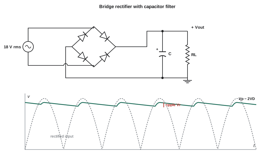
A full-wave rectifier uses both half-cycles. The center-tapped version uses a transformer with a tapped secondary and two diodes: each half of the winding drives the load through its own diode on alternate half-cycles. Only one diode drop is lost, but each half of the winding is used only half the time, and each diode must block 2V_p. The bridge rectifier uses an ordinary secondary and four diodes arranged so that on each half-cycle two of them conduct in series with the load. It loses two diode drops, but uses the whole winding all the time, and each diode blocks only about V_p. Bridges are packaged as single four-terminal parts and are by far the most common choice.
| Rectifier | Diodes conducting | Output peak | Diode PIV | Ripple frequency |
|---|---|---|---|---|
| Half-wave | 1 | V_p − V_D | ≈ 2V_p (with capacitor) | f (60 Hz) |
| Full-wave center-tapped | 1 per half-cycle | V_p − V_D | ≈ 2V_p | 2f (120 Hz) |
| Bridge | 2 per half-cycle | V_p − 2V_D | ≈ V_p | 2f (120 Hz) |
The capacitor filter and ripple
A rectifier alone produces a pulsating voltage that falls to zero twice a cycle, far too rough for electronics. A large capacitor across the output fixes this. Near each peak the rectifier charges the capacitor to V_p minus the diode drops. As the input falls away from its peak, the diodes become reverse biased, and the capacitor alone supplies the load, its voltage drooping as it discharges. When the next peak arrives the diodes conduct again and top it up. The output is DC with a small sawtooth ripple riding on it.
If the ripple is small, the capacitor discharges at a nearly constant current I_L for nearly the whole period between peaks, T = 1/(2f) for a full-wave rectifier. The charge lost is I_L T = C V_r, which gives the peak-to-peak ripple:
The DC output is approximately the peak minus half the ripple, V_DC ≈ V_p − 2V_D − V_r/2 for a bridge. These formulas slightly overestimate ripple because the capacitor is recharging for part of the period, which makes them a safe basis for design.
Worked problem
Filter capacitor for the 24 V rail
The bridge rectifier is fed from an 18 V RMS secondary at 60 Hz. The load draws 1.2 A when all LED signal heads are lit. The diodes drop 1.0 V each at this current. Choose a capacitor so the ripple is no more than 2.5 V peak-to-peak, and find the DC output and the minimum of the ripple.
Show solution
- \[V_p = \sqrt{2} \times 18 = 25.5\ \text{V}\]
- \[V_{peak,out} = 25.5 - 2(1.0) = 23.5\ \text{V}\]
- \[C \ge \frac{I_L}{2fV_r} = \frac{1.2}{2 \times 60 \times 2.5} = 4000\ \mu\text{F}\]
- Choose a standard 4,700 µF capacitor, which gives
- \[V_r = \frac{1.2}{2 \times 60 \times 0.0047} \approx 2.13\ \text{V}\]
- \[V_{DC} \approx 23.5 - \frac{2.13}{2} \approx 22.4\ \text{V}, \quad V_{min} \approx 21.4\ \text{V}\]
Answer: A 4,700 µF capacitor gives about 2.1 V of ripple, a DC level near 22.4 V and a minimum near 21.4 V at nominal line. Amara must repeat the check at low line, where every voltage drops by roughly 15 percent, to make sure the regulators downstream still have enough headroom.
Diode current: short, tall pulses
The capacitor filter has a hidden cost. The diodes conduct only during the short interval near each peak when the input exceeds the capacitor voltage. In that brief window they must replace all the charge the load drew over the whole half-cycle, so the current flows in short, tall pulses, often five to ten times the average load current. The conduction interval can be estimated from the ripple: the diodes conduct while the sine rises from V_p − V_r to V_p, a phase angle of about √(2V_r/V_p) radians before the peak.
These pulses matter in three ways. The diodes and transformer must handle their RMS current, which is much larger than the average and causes extra heating. The pulses distort the current drawn from the mains, which is why larger supplies need power-factor correction. And the capacitor must be rated for the RMS ripple current, or it will overheat and its life will be short. Electrolytic capacitor life roughly halves for every 10 °C rise in temperature, so ripple current rating and cabinet temperature are among the most important numbers in a supply design.
import math
f, Vrms, Vd, C, IL = 60.0, 18.0, 1.0, 4700e-6, 1.2
Vp = math.sqrt(2) * Vrms
w = 2 * math.pi * f
dt = 1e-6
v = Vp - 2 * Vd                       # start fully charged
vmin, vmax, ipk, charge_time = 1e9, 0, 0, 0
t = 0.0
while t < 0.1:                        # simulate 100 ms (6 cycles)
    vin = abs(Vp * math.sin(w * t)) - 2 * Vd
    if vin > v:                       # diodes conduct: capacitor follows input
        i_d = C * (vin - v) / dt + IL
        v = vin
        if t > 0.05:
            ipk = max(ipk, i_d); charge_time += dt
    else:                             # diodes off: capacitor feeds load
        v -= IL * dt / C
    if t > 0.05:
        vmin, vmax = min(vmin, v), max(vmax, v)
    t += dt
print(f"simulated ripple {vmax - vmin:.2f} V p-p, minimum {vmin:.2f} V")
print(f"formula ripple   {IL / (2 * f * C):.2f} V p-p")
print(f"diodes conduct {charge_time / 0.05 * 100:.0f} % of the time, peak current about {ipk:.0f} A")simulated ripple 1.86 V p-p, minimum 21.60 V formula ripple 2.13 V p-p diodes conduct 13 % of the time, peak current about 18 A
The simulation confirms the hand calculation and shows the pulse problem plainly: the diodes conduct for only a small fraction of each cycle, and the peak current is many times the 1.2 A average. In a real circuit the transformer's winding resistance and leakage inductance round off and lower these peaks, which is why a simulation with an ideal source is pessimistic. Daniel still insists that the bridge be rated for at least the full-load peak current and the inrush at power-up.
Inrush current and surge ratings
When the supply is first switched on, the filter capacitor is empty, and for the first few half-cycles the rectifier charges it as fast as the transformer resistance allows. This inrush can be tens of amps for a 4,700 µF capacitor. The bridge's non-repetitive surge rating, I_FSM, often specified for one half-cycle of 60 Hz, must exceed it. Small transformers limit inrush by their own winding resistance; larger supplies add a negative-temperature-coefficient thermistor, whose resistance is high when cold and falls as it warms, or an active soft-start circuit.
Voltage multipliers and other rectifier circuits
Diodes and capacitors can also build voltages higher than the input peak. A voltage doubler charges one capacitor on the positive half-cycle and another on the negative, and stacks them; a cascade of such stages, the Cockcroft-Walton multiplier, produces kilovolts for photomultiplier tubes, ionizers and old television sets. These circuits supply only small currents, because the output falls quickly as load increases. At the other end of the scale, synchronous rectifiers replace diodes with MOSFETs that are switched on at the right moments, cutting the rectifier loss to a few tens of millivolts, which matters a great deal in a low-voltage, high-current supply such as the one feeding a processor.
From unregulated to regulated
The filtered output still has ripple and still follows the mains and the load. LEDs and relays tolerate that, but logic, sensors and amplifiers need a steady rail. A linear regulator does this by acting as a variable resistor in series with the load, dropping whatever voltage is needed to hold its output constant. Its key limits are the dropout voltage, the minimum difference between input and output for it to keep regulating, and its dissipation, (V_in − V_out) × I_out. A 12 V regulator with a 2 V dropout needs at least 14 V at the bottom of the ripple at low line. Lesson 4 builds the simplest regulator, the Zener shunt, and shows how a transistor improves it.
Worked problem
Headroom at low line
At low line (102 V instead of 120 V), all transformer voltages scale down by 102/120 = 0.85. Using the previous example's design, find the ripple minimum at low line and check whether a 12 V regulator with 2 V dropout still regulates.
Show solution
- \[V_p = 0.85 \times 25.5 = 21.7\ \text{V}\]
- \[V_{peak,out} = 21.7 - 2.0 = 19.7\ \text{V}\]
- The ripple depends on load current and capacitance, not line voltage, so it is still about 2.1 V.
- \[V_{min} \approx 19.7 - 2.1 = 17.6\ \text{V} > 12 + 2 = 14\ \text{V}\]
Answer: The minimum of about 17.6 V leaves more than 3 V of margin above the regulator's 14 V requirement, even at low line and full load.
Supplies that plug into the mains are subject to safety standards for insulation, creepage distances, fusing and temperature. Using a pre-certified external supply or transformer, as Cedarline does for the cabinet, avoids much of that work, but the engineer still owns the choice of fuse, the wiring and the thermal design inside the controller.
Common mistakes
MistakeForgetting that ratings refer to RMS values while the rectifier responds to peaks.
InsteadMultiply RMS by √2 before calculating the DC output.
MistakeIgnoring the two diode drops in a bridge.
InsteadA bridge loses about 1.4 to 2 V, which is significant on low-voltage supplies.
MistakeChoosing diodes by average current only.
InsteadCheck repetitive peak and surge current; the capacitor filter makes the diode current pulsed.
MistakeCalculating only at nominal line and typical load.
InsteadRepeat at low line and full load for headroom, and at high line and light load for maximum voltage and dissipation.
Summary and key terms
- A linear DC supply is a transformer, rectifier, filter capacitor and regulator.
- Half-wave rectifiers waste half the cycle; full-wave center-tapped and bridge rectifiers use both halves.
- A bridge loses two diode drops but uses the whole winding, and each diode blocks only about V_p.
- Ripple with a capacitor filter is about I_L/(2fC) for full-wave rectification.
- Diode and capacitor currents flow in short, tall pulses; check peak, RMS and surge ratings.
- Design at low line and full load for headroom, and at high line for maximum stress.
- Rectifier
- A circuit that converts AC into unidirectional, pulsating DC.
- Bridge rectifier
- Four diodes arranged so two conduct on each half-cycle, giving full-wave output from a single winding.
- Ripple
- The residual AC variation on a filtered DC output.
- Peak inverse voltage
- The largest reverse voltage a rectifier diode must block.
- Inrush current
- The large current that charges the filter capacitor at switch-on.
- Dropout voltage
- The minimum input-to-output difference at which a linear regulator still regulates.
- Voltage multiplier
- A diode–capacitor circuit that produces a DC output higher than the AC input peak.
Practice problems
Work each problem on paper first, then reveal the answer to check.
A 12 V RMS secondary feeds a bridge with 0.8 V diodes. Find the peak output.
Show answer
√2 × 12 − 1.6 = 16.97 − 1.6 ≈ 15.4 V.
Find the ripple for a 500 mA load, a 2,200 µF capacitor and full-wave rectification at 60 Hz.
Show answer
0.5 / (120 × 0.0022) ≈ 1.9 V peak-to-peak.
What PIV must the diodes of a center-tapped rectifier withstand if each half winding has a 20 V peak?
Show answer
About 2 × 20 = 40 V; choose at least a 100 V part.
Why is half-wave rectification rarely used for power supplies?
Show answer
It needs twice the capacitance for the same ripple, puts DC through the transformer and wastes half the cycle.
A supply is designed for 50 Hz mains but used at 60 Hz. Does the ripple rise or fall?
Show answer
It falls, because the capacitor is recharged more often.
Why does capacitor ripple current rating matter in a hot traffic cabinet?
Show answer
Ripple current heats the capacitor, and electrolytic life roughly halves for each 10 °C rise.
Lesson quiz · 5 questions
Score 60% or more to complete this lesson.
Create a free account to save your progress, take quizzes and earn a certificate.