
DCT-220 · Lesson 9 of 12 · 20 min
Remote power panels, busways and branch circuits
The last part of the facility's distribution, before the rack's own PDUs, is the branch circuit: the breaker, cable or busway tap-off and receptacle that supply one rack, or one side of one rack. Branch circuits are where capacity planning meets daily work. Every new installation in a hall needs branches, every customer power request is measured against them, and many alarms and trips begin here. This lesson covers the two main ways Stonebridge distributes power across a hall, remote power panels and overhead busways, and the rules technicians use to check that a branch can carry a planned load.
Remote power panels
A remote power panel (RPP) is a cabinet of branch circuit breakers placed within a row of racks or at its end, fed by a large cable from a floor PDU. It extends the PDU's panelboards closer to the racks, so the branch cables are shorter and the PDU itself can sit in a gallery or along the hall wall. Hall A uses floor PDUs with built-in panelboards for most rows and RPPs for its newer rows, each RPP holding up to 84 branch breakers with branch current monitoring. RPPs are named after their source: RPP-A2-03 is the third RPP fed from the Hall A A-side distribution.
Branch cables run from the RPP or PDU breakers, usually overhead in cable trays in Hall A's newer rows, or under the raised floor in its older ones, to receptacles above or below each rack. A typical Hall A rack has one 208 V, 30 A three-phase branch per side, ending in a locking receptacle that matches the plug on the customer's rack PDU. Each branch breaker, cable and receptacle has the same label.
Overhead busways
In Halls B, C and D, power reaches the racks through overhead busways. A busway is a long metal enclosure containing copper or aluminum busbars, running along the row above the racks. Along its length are slots at regular intervals into which tap-off boxes can be plugged. Each tap-off box contains a breaker and a cord or receptacle for one rack. To add power to a new rack, an electrician installs a tap-off box in the nearest slot, rather than running a new cable from a panel. Busways make it easy to change the power layout as customers come and go, and they keep the space under and between racks clear.
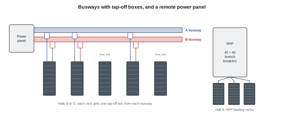
Each row in Halls B to D has an A busway and a B busway. Hall D's busways carry 415Y/240 V and are rated for very high currents, because each Corvid AI rack draws about 132 kW. Some tap-off boxes in Hall D feed one rack with several three-phase circuits. Busways are installed and their tap-off boxes added or removed by electricians, usually with the busway energized using tap-off boxes designed for live insertion, under a permit and with the arc flash precautions described in DCT-120. Where a procedure calls for it, the busway feed is locked out instead, as it was for the Hall D installation in the DCT-120 capstone.
Branch circuit ratings and the 80 % rule
A branch circuit is rated by its breaker: a 30 A breaker protects a circuit whose cable and receptacle are rated for 30 A. Data center loads run continuously, and the National Electrical Code limits continuous loads on most breakers to 80 % of their rating, unless the breaker and its enclosure are specifically rated for 100 % continuous duty. A 30 A breaker can therefore carry 24 A continuously. Stonebridge's capacity rules use this as the absolute ceiling, and add the 2N requirement on top: each side of a rack must be able to carry the whole rack's load if the other side fails.
That gives the per-side planning limit used in DCT-110 and DCT-130. If a rack has a 30 A branch on each side, the rack's total load must not exceed 24 A, so that either side can carry it alone. In normal operation each side carries about half, 12 A, or 40 % of the breaker rating. A side reading above 40 % in normal operation means the rack would exceed 80 % on one side if the other failed.
import math
# What can a 2N pair of branch circuits carry? (three-phase branches, PF 0.95)
branches = [  # (name, volts L-L, breaker A)
    ("Hall A 208 V 30 A", 208, 30), ("Hall A 208 V 60 A", 208, 60),
    ("Halls B/C 415 V 32 A", 415, 32), ("Hall D 415 V 125 A", 415, 125),
]
pf = 0.95
for name, v, amps in branches:
    cont = 0.8 * amps                          # continuous limit on one side
    kw_one_side = math.sqrt(3) * v * cont * pf / 1000
print(f"{name:22s}: one side can carry {kw_one_side:6.1f} kW continuously; plan the rack at or below that, about {kw_one_side / 2:5.1f} kW per side in normal operation")Hall A 208 V 30 A : one side can carry 8.2 kW continuously; plan the rack at or below that, about 4.1 kW per side in normal operation Hall A 208 V 60 A : one side can carry 16.4 kW continuously; plan the rack at or below that, about 8.2 kW per side in normal operation Halls B/C 415 V 32 A : one side can carry 17.5 kW continuously; plan the rack at or below that, about 8.7 kW per side in normal operation Hall D 415 V 125 A : one side can carry 68.3 kW continuously; plan the rack at or below that, about 34.1 kW per side in normal operation
The figures show why higher voltage matters for dense racks. A 208 V, 30 A branch carries under 9 kW of rack load; a 415 V, 125 A branch carries about 66 kW. Hall D's 132 kW racks have two such circuits per side.
Voltage drop
Current flowing through a cable loses some voltage along the way, in proportion to the current, the length and the cable's resistance. Long branch circuits at low voltage and high current can lose enough voltage to matter. Electrical codes recommend keeping voltage drop on branch circuits within a few percent, and designers size cables accordingly. Technicians do not size cables, but they see voltage drop in the readings: a rack PDU reading noticeably lower voltage than the RPP feeding it, at high load, can point to a long or undersized cable or, more seriously, a loose connection that is heating up.
import math
# Voltage drop on a three-phase branch circuit (copper, illustrative resistance values)
v_ll = 208.0
cases = [  # (description, current A, length ft, ohms per 1,000 ft for the conductor size)
    ("A-31-03, 10 AWG, short run", 22, 50, 1.04),
    ("A-36-11, 10 AWG, long run", 22, 180, 1.04),
    ("A-36-11 resized to 8 AWG", 22, 180, 0.65),
]
for name, amps, length, r in cases:
    drop = math.sqrt(3) * amps * r * length / 1000
print(f"{name:28s}: {drop:4.1f} V drop, {drop / v_ll * 100:.1f} %")A-31-03, 10 AWG, short run : 2.0 V drop, 1.0 % A-36-11, 10 AWG, long run : 7.1 V drop, 3.4 % A-36-11 resized to 8 AWG : 4.5 V drop, 2.1 %
Loose connections and hot spots
A loose or corroded connection in a branch circuit has a higher resistance than it should. At high current it heats, the heat makes the connection worse, and eventually it can melt insulation, start a fire, or fail open. Connections at receptacles, tap-off boxes and breaker terminals are the usual places. Stonebridge has its electricians carry out infrared thermography surveys of the distribution equipment each year, scanning for connections that run hotter than their neighbors; some busways and RPPs also have built-in temperature sensors. Between surveys, technicians watch for the signs: a smell of hot plastic, discolored or deformed receptacles or plugs, a buzzing sound from a tap-off box, a branch voltage reading that is low at high load, or an alarm from a busway temperature sensor.
| Sign | Possible cause | Action |
|---|---|---|
| Hot smell near a rack's power whip or tap-off | Overheating connection or overloaded plug | Do not touch; report urgently; if smoke, raise the alarm |
| Discolored or deformed receptacle or plug | Past overheating | Report; electrician inspects with the branch de-energized |
| Buzzing from a tap-off box | Loose connection or failing breaker | Report urgently |
| Branch voltage low only at high load | High resistance in the circuit | Report; thermographic check |
| Busway temperature alarm | Overload or hot joint | Read the alarm details; report to critical facilities |
Branch current monitoring and capacity planning
Most RPPs, PDUs and busway tap-off boxes at Stonebridge measure the current on every branch. The monitoring system trends these readings and raises alarms at set thresholds, typically a warning at 40 % per side and an alarm at 50 % per side on 2N branches, well before the 80 % limit is in danger. The capacity planning team uses the same data to decide which branches can take new load and where to place new racks. Every power-related ticket a technician handles, from a customer asking for more power to a rack being decommissioned, updates this picture.
# Branch monitoring report for a row: flag 2N pairs above the per-side planning limit (illustrative)
row = {  # rack: (A-side amps, B-side amps, breaker rating A)
    "A-36-01": (8.2, 8.0, 30), "A-36-03": (11.6, 11.9, 30), "A-36-05": (13.4, 12.8, 30),
    "A-36-07": (0.0, 21.5, 30), "A-36-09": (6.1, 6.3, 30), "A-36-11": (15.8, 15.2, 30),
}
for rack, (a, b, rating) in row.items():
    total = a + b
    issues = []
    if a == 0 or b == 0: issues.append("one side reads zero: check cords and breakers")
    if max(a, b) > 0.4 * rating and min(a, b) > 0: issues.append("above 40 % per side")
    if total > 0.8 * rating: issues.append("rack load exceeds what one side can carry")
print(f"{rack}: A {a:4.1f} A, B {b:4.1f} A, total {total:4.1f} A -> " + ("; ".join(issues) if issues else "within plan"))A-36-01: A 8.2 A, B 8.0 A, total 16.2 A -> within plan A-36-03: A 11.6 A, B 11.9 A, total 23.5 A -> within plan A-36-05: A 13.4 A, B 12.8 A, total 26.2 A -> above 40 % per side; rack load exceeds what one side can carry A-36-07: A 0.0 A, B 21.5 A, total 21.5 A -> one side reads zero: check cords and breakers A-36-09: A 6.1 A, B 6.3 A, total 12.4 A -> within plan A-36-11: A 15.8 A, B 15.2 A, total 31.0 A -> above 40 % per side; rack load exceeds what one side can carry
Three racks need attention. A-36-07 has a dead A side, perhaps a cord unplugged or a tripped branch, and its whole load on B; that is a redundancy problem to fix today. A-36-05 and A-36-11 are above the per-side planning limit, and A-36-11's total load of 31 A is more than one 30 A side can carry at 80 %: if either of its sides failed, the other would overload and trip, dropping the rack. That is a customer conversation about power or load reduction, opened as a capacity ticket.
Work on branch circuits
Installing, moving or removing branch circuits, tap-off boxes and receptacles is electrical work done by electricians under permit. The technician's part is to prepare: confirm the rack and side, confirm the partner side is healthy and carrying the rack, notify the customer, and check after the work that the new branch is labeled, the monitoring shows it, and the rack PDU on that side reads the expected voltage. Technicians must never plug a rack PDU into the wrong side's receptacle, which would put both of a rack's cords on the same path. DCT-130's capstone caught exactly that mistake on a Hall D rack before power-on.
Worked problem
A capacity request in Hall A
Bayview Credit Union asks to add two servers to rack A-31-03, each with two power supplies drawing about 450 W in normal use and 700 W at peak. The rack's two 208 V, 30 A branches now read 9.8 A on A and 9.6 A on B.
Show solution
- Jamal works out the new load conservatively at peak: two servers × 700 W = 1,400 W.
- At 208 V three-phase and power factor 0.95, 1,400 W is about 1,400 / (1.732 × 208 × 0.95) = 4.1 A of three-phase current for the rack.
- Present total load is 9.8 + 9.6 = 19.4 A. Adding 4.1 A gives 23.5 A.
- The limit for the rack is what one side can carry: 80 % of 30 A = 24 A. 23.5 A is just under it.
- In normal operation each side would carry about 11.8 A, 39 % of its rating, inside the 40 % planning limit.
Answer: The request fits, with very little margin. Jamal approves it under the rule but adds a note to the ticket: any further equipment in A-31-03 will need a larger branch circuit or a second rack, and the customer's account manager should raise this before Bayview plans its next change.
Common mistakes
MistakePlanning a rack's load against the sum of both sides' ratings.
InsteadEach side must be able to carry the whole rack: plan against one side's 80 % limit.
MistakeIgnoring a branch that reads zero because the rack is still up.
InsteadOne side is dead; the rack has no redundancy.
MistakePlugging both cords of a device into one side.
InsteadCheck the receptacle labels: one cord to A, one cord to B.
MistakeTouching a discolored receptacle to see if it is hot.
InsteadReport it; the electrician inspects it de-energized.
MistakeAssuming busway tap-off boxes can be added by anyone.
InsteadBusway work is electrical work under permit.
Summary and key terms
- Remote power panels and floor PDU panelboards feed racks through branch breakers, cables and labeled receptacles.
- Overhead busways carry power along a row; tap-off boxes in their slots feed individual racks.
- Continuous loads are limited to 80 % of breaker rating, and each side of a 2N rack must carry the whole rack.
- In normal operation, each side of a 2N branch pair should be at or below about 40 % of its rating.
- Voltage drop and loose connections show up as low voltage at load, heat, smells and discoloration.
- Branch current monitoring drives capacity planning, and every power ticket updates it.
- Remote power panel
- A cabinet of branch breakers placed near the racks and fed from a PDU.
- Busway
- An overhead enclosure of busbars with slots for plug-in tap-off boxes.
- Tap-off box
- A box containing a breaker and cord or receptacle that plugs into a busway slot.
- Branch circuit
- The final circuit from a breaker to the receptacle feeding a rack.
- Continuous load
- A load expected to run at its maximum current for three hours or more.
- Thermography
- Using an infrared camera to find hot spots in electrical equipment.
Practice problems
Work each problem on paper first, then reveal the answer to check.
How much current may a 30 A branch carry continuously under the 80 % rule?
Show answer
24 A.
A rack's A and B branches read 13 A each on 30 A breakers. Is it within the 2N plan?
Show answer
No: the total, 26 A, exceeds 24 A, so one side could not carry the rack alone.
Why do busways suit halls where layouts change often?
Show answer
Tap-off boxes can be added or moved in existing slots without running new cables.
What might a low voltage at a rack PDU only at high load indicate?
Show answer
Excessive voltage drop or a high-resistance, possibly loose, connection.
Lesson quiz · 5 questions
Score 60% or more to complete this lesson.
Create a free account to save your progress, take quizzes and earn a certificate.