
DCT-220 · Lesson 8 of 12 · 19 min
Automatic transfer switches and the transfer sequence
A generator that starts but is not connected to the load does nothing. The equipment that decides when the utility has failed, starts the generators, connects them to the load, and later returns the load to the utility, is the transfer system. In smaller buildings this is an automatic transfer switch (ATS). In large data centers it is often a set of motor-operated breakers in paralleling switchgear controlled by a programmable controller, but the logic is the same. This lesson walks through the transfer sequence second by second, explains open and closed transitions and retransfer, and shows what the technician sees on the screens and in the logs.
The automatic transfer switch
An ATS has two inputs, normal (the utility) and emergency (the generator), and one output to the load. It contains a switching mechanism that connects the output to one input or the other, and a controller that monitors both sources. When the normal source fails or goes outside its voltage and frequency limits for longer than a set delay, the controller signals the generator to start. When the generator's voltage and frequency are within limits, the controller transfers the load to the emergency source. When the normal source returns and stays stable for a set time, the controller transfers the load back and, after a cool-down period, stops the generator.
At Stonebridge, the Hall A block uses ATS units for its mechanical and house loads and motor-operated breakers in the generator switchboard for the UPS inputs. Halls B, C and D use medium-voltage paralleling switchgear: all the generators of a block are synchronized onto a common generator bus, and motor-operated breakers transfer each unit substation from utility to generator bus. Both arrangements follow the sequence below.
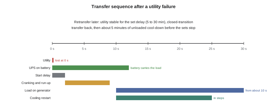
The sequence after a utility failure
| Time (typical) | What happens | What the technician sees |
|---|---|---|
| 0 s | Utility voltage lost on both lines | Lights in non-UPS areas go out briefly or flicker; UPS systems on battery; alarms |
| 0 to 2 s | Transfer controller confirms the loss and waits out its start delay | Utility-lost alarm on the controller |
| 2 s | Start signal to all generators | Generator controllers show cranking |
| 3 to 5 s | Engines fire and accelerate | Engine running, speed rising |
| 7 to 10 s | Generators reach voltage and frequency; paralleling gear synchronizes and closes them onto the bus | Generator ready, breaker closed indications |
| 10 s | Transfer breakers or ATS connect the load to the generators | Load on generator; UPS inputs see voltage again |
| 10 to 30 s | UPS rectifiers ramp up gradually; mechanical loads restart in planned steps | UPS from battery to normal; chillers, CRAHs, pumps restarting |
| Minutes later | UPS batteries recharging; plant stable on generator | Battery charging; generator loads steady |
The load is applied to the generators in steps, not all at once. A diesel generator's frequency dips when a large load is suddenly added, and too large a step can cause a dip big enough to trip loads or stall the engine. UPS rectifiers therefore walk in their load over several seconds, and the mechanical plant's chillers, pumps and fans are restarted by the building management system in a sequence planned during commissioning. The cooling restart is critical: the IT load keeps producing heat throughout, and halls without cooling warm up quickly, especially the dense AI racks in Hall D, which is why Hall D's coolant pumps and CDUs are on UPS.
# Simulate a transfer sequence and check the total time to load (illustrative timings, seconds)
events = [
    ("utility lost", 0.0),
    ("start delay ends, start signal", 2.0),
    ("engines firing", 2.0 + 1.6),
    ("first generator at voltage and frequency", 2.0 + 6.4),
    ("paralleled sets on bus", 2.0 + 7.2),
    ("transfer to generator", 2.0 + 7.6),
]
ups_runtime_s = 23.0 * 60
for name, t in events:
    print(f"{t:6.1f} s  {name}")
t_load = events[-1][1]
print(f"Load on generator after {t_load:.1f} s; UPS battery reserve at present load {ups_runtime_s / 60:.1f} min")
print(f"Battery reserve used: {t_load / ups_runtime_s * 100:.1f} %")0.0 s utility lost 2.0 s start delay ends, start signal 3.6 s engines firing 8.4 s first generator at voltage and frequency 9.2 s paralleled sets on bus 9.6 s transfer to generator Load on generator after 9.6 s; UPS battery reserve at present load 23.0 min Battery reserve used: 0.7 %
Under ten seconds of the roughly twenty-three-minute battery reserve are used in a normal transfer. The reserve is there for when the sequence does not go normally: a generator fails to start, a breaker fails to close, or the paralleling controller needs a second attempt.
Open and closed transition
When an ATS transfers from one live source to another, it can do so in two ways. In an open transition, also called break-before-make, the switch disconnects from the first source before connecting to the second, leaving the load without power for a fraction of a second. For loads on UPS, this short break is covered by the batteries. In a closed transition, or make-before-break, the switch connects to the second source before disconnecting from the first, so the two sources are briefly paralleled. Closed transition needs the two sources to be synchronized and is limited to a fraction of a second by utility rules, because the generator is briefly connected to the utility network.
After a utility failure, the first transfer is always an open transition, because the utility is dead. Closed transition matters on the way back: when the utility returns, a closed-transition retransfer moves the load back to the utility without the second interruption an open transition would cause. Stonebridge's transfer equipment uses closed-transition retransfer, approved by Dominion Energy under the interconnection agreement. Some ATS units offer delayed transition, which pauses in a neutral position to let motor loads slow down before reconnecting, protecting motors from out-of-phase reconnection.
Retransfer and cool-down
When the utility comes back, the transfer controls do not return the load immediately. Utility supplies often come back and fail again several times while crews restore the network. The controller waits for the utility to be stable for a set time, the retransfer delay, before moving the load back. Common settings range from five to thirty minutes; Stonebridge uses thirty minutes after a storm-related outage and lets the operations team extend it if the utility advises that more switching is planned. After retransfer, the generators run unloaded for a cool-down period, typically five minutes, so that the engines cool evenly before stopping. The controller then stops the sets and returns them to automatic, ready for the next event.
Many sites choose not to retransfer automatically at all after a major event, but to keep the load on generator until the operations team decides the utility is reliable. The decision weighs the risk of another utility failure against the generator run hours, fuel and emissions. Whatever the policy, it is written into the site procedures so that nobody improvises during an event.
Controller settings a technician should know
The transfer controller holds a set of timers and limits. Technicians do not change them, but knowing them makes the logs readable. The values below are typical; each site's are recorded in its operating procedures.
| Setting | Typical value | Purpose |
|---|---|---|
| Utility undervoltage pickup | About 85 to 90 % of nominal | Below this, the utility is treated as failed |
| Start delay | 1 to 3 seconds | Ignores brief interruptions and utility reclosing |
| Generator ready | Voltage within about 90 % and frequency within about 1 to 2 Hz of nominal | Load is transferred only to a stable generator |
| Transfer to emergency delay | 0 to a few seconds | Lets several generators parallel before load is applied |
| Retransfer delay | 5 to 30 minutes | Waits for the utility to be stable |
| Cool-down | About 5 minutes | Unloaded running before the engine stops |
| Exercise timer | Monthly, if enabled | Starts the generator for a scheduled test |
Paralleling switchgear
In a paralleling plant, each generator has its own breaker onto a common generator bus. The first set to reach voltage and frequency closes onto the dead bus. Each following set is synchronized by its controller: the controller adjusts the engine speed until the set's frequency and phase angle match the bus, then closes its breaker at the right moment. Once enough sets are on the bus to carry the load, the transfer breakers close. If one set fails, the load is shared by those that are running, and if the remaining capacity is not enough, the controller sheds the lowest-priority loads, such as office lighting and some mechanical equipment, to protect the critical load.
# Paralleling plant: is there enough capacity after a failed start? Which loads are shed? (illustrative)
sets = {"GEN-C1": 3000, "GEN-C2": 3000, "GEN-C3": 3000, "GEN-C4": 3000, "GEN-C5": 3000}
failed = ["GEN-C4"]
loads = [  # (priority, load, kW) - priority 1 is most critical
    (1, "UPS inputs, Halls B and C", 7200), (1, "cooling for Halls B and C", 3300),
    (2, "office and support areas", 250), (3, "car park lighting and heaters", 220),
]
available = sum(kw for g, kw in sets.items() if g not in failed) * 0.9   # plan to 90 % of rating
running = 0
for prio, name, kw in sorted(loads):
    if running + kw <= available:
        running += kw
        print(f"keep   priority {prio}: {name:32s}{kw:6.0f} kW")
    else:
        print(f"SHED   priority {prio}: {name:32s}{kw:6.0f} kW")
print(f"Available {available:,.0f} kW, carried {running:,.0f} kW ({running / available * 100:.0f} %)")keep priority 1: UPS inputs, Halls B and C 7200 kW keep priority 1: cooling for Halls B and C 3300 kW keep priority 2: office and support areas 250 kW SHED priority 3: car park lighting and heaters 220 kW Available 10,800 kW, carried 10,750 kW (100 %)
With one of the five sets failed, the four remaining can carry all the critical load and the support areas, so only the car park lighting is shed. This is the N+1 design doing its job. If a second set failed, more load would have to be shed, and the redundancy whiteboard would turn red.
Bypass-isolation ATS units
ATS units serving critical loads are often the bypass-isolation type. A second switch inside the same enclosure can carry the load while the main transfer switch is withdrawn for maintenance or repair, without interrupting power. Operating a bypass-isolation ATS is done by trained critical facilities staff with a procedure, much like a UPS maintenance bypass. The ATS front shows which source is connected, the position of the bypass switch, and any alarms.
What to watch and record during a transfer
- The time the utility was lost and the time the load was on generator, from the controller or monitoring system.
- Which generators started, how long each took to be ready, and any that failed.
- UPS battery time used, and the battery state of charge as recharging begins.
- Cooling restart: CRAH, chiller and CDU restart times and any hall temperature rise.
- Any load shedding and which loads were affected.
- When the utility returned, when retransfer happened and how long the generators ran.
The monitoring system records all of this, but during a real event the technician's written notes of what was seen and heard are often what makes the incident report clear. Lesson 12 follows a full event and the report that comes after it.
Worked problem
Reading a transfer log after a test
During the annual pull-the-plug test of the Hall A block, the operations team opens the utility breaker on purpose to simulate a utility failure, with all customers notified. Jamal records the controller and monitoring screens.
Show solution
- Utility breaker opened at 10:00:00.0. UPS-A2 and UPS-B2 on battery at 10:00:00.1.
- Start signal at 10:00:02.0. GEN-A1 ready at 10:00:09.4, GEN-A2 at 10:00:09.8, GEN-A3 at 10:00:10.1.
- Generator bus closed and load transferred at 10:00:10.6. UPS rectifiers ramped up over 8 seconds; UPS back to normal at 10:00:19.
- CRAH units restarted in groups between 10:00:12 and 10:00:31. Hall A cold aisle temperature rose by 1.4 °F and recovered within three minutes.
- Utility breaker closed at 10:30:00. After the test's shortened 2-minute stability delay, a closed-transition retransfer returned the load to the utility at 10:32:00. The generators cooled down for 5 minutes and stopped at 10:37.
Answer: The block transferred in 10.6 seconds, using under 1 % of the battery reserve, and the cooling restart kept the hall well within limits. The test's report records these times next to last year's: GEN-A3's time to ready improved by nearly five seconds since its block heater thermostat was replaced.
Common mistakes
MistakeExpecting the load to return to the utility the moment it comes back.
InsteadThe retransfer delay waits for the utility to be stable.
MistakeThinking closed transition is used after a utility failure.
InsteadThe first transfer is open; closed transition is used on retransfer.
MistakeAssuming all loads come back at once on generator.
InsteadLoads are stepped on to avoid large frequency dips.
MistakeForgetting the cooling during a transfer.
InsteadRecord cooling restart times and hall temperatures; heat builds quickly.
MistakeChanging a controller timer to speed things up.
InsteadSettings are part of the design and are changed only through engineering review.
Summary and key terms
- The transfer system detects utility failure, starts the generators, transfers the load, and later retransfers it.
- A normal transfer takes about ten seconds, covered by the UPS batteries.
- Loads are applied in steps, and the cooling restart sequence is critical.
- Open transition breaks before making; closed transition parallels briefly and is used for retransfer.
- Retransfer waits for a stable utility, and generators cool down unloaded before stopping.
- Paralleling switchgear synchronizes generators onto a bus and sheds low-priority loads if capacity falls short.
- Automatic transfer switch
- A switch that transfers a load between a normal and an emergency source automatically.
- Open transition
- A transfer that disconnects from one source before connecting to the other.
- Closed transition
- A transfer that briefly parallels the two sources so there is no interruption.
- Retransfer delay
- The time the utility must be stable before the load is returned to it.
- Paralleling switchgear
- Switchgear that synchronizes several generators onto a common bus.
- Load shedding
- Disconnecting lower-priority loads to protect critical loads when capacity is short.
Practice problems
Work each problem on paper first, then reveal the answer to check.
Why does the transfer controller wait a second or two before starting the generators?
Show answer
To ignore brief interruptions and utility reclosing.
Why is closed transition used for retransfer but not for the first transfer?
Show answer
On the first transfer the utility is dead; closed transition needs two live, synchronized sources.
What is a cool-down period?
Show answer
Unloaded running of the generator, about five minutes, before it stops.
If one of five 3,000 kW sets fails, how much capacity is available at a 90 % planning limit?
Show answer
4 × 3,000 × 0.9 = 10,800 kW.
Lesson quiz · 5 questions
Score 60% or more to complete this lesson.
Create a free account to save your progress, take quizzes and earn a certificate.