
DCE-340 · Lesson 7 of 12 · 34 min
Transfer switches and paralleling
A generator is useless until something connects it to the load at the right moment and disconnects the utility at the same time. That is the job of transfer equipment, from a simple automatic transfer switch serving one distribution board to a lineup of medium-voltage paralleling switchgear that synchronizes a dozen generators onto a common bus. Transfer equipment also has to put everything back when the utility returns, ideally without the load noticing. This lesson covers transfer switch types and ratings, the sequence of operation during an outage, paralleling and synchronizing, load sharing and load management, and interconnection with the utility.
Automatic transfer switches
An automatic transfer switch (ATS) is a switching device with two sources, normal (utility) and emergency or standby (generator), and one load connection. Its controller monitors both sources and transfers the load when the normal source fails and the alternate source is acceptable. ATSs range from 30 A units in small buildings to 4000 A units feeding a data center switchboard. Larger facilities use pairs of circuit breakers (a utility main and a generator main, electrically interlocked) in switchgear to perform the same function, which allows higher ratings and better protection.
Transfer switches in the US are listed to UL 1008, Transfer Switch Equipment. The NEC requires transfer equipment for emergency systems to be listed for emergency use and to prevent inadvertent interconnection of the normal and emergency sources (700.5); Articles 701 and 702 contain similar requirements for legally required and optional standby systems.
Transition types
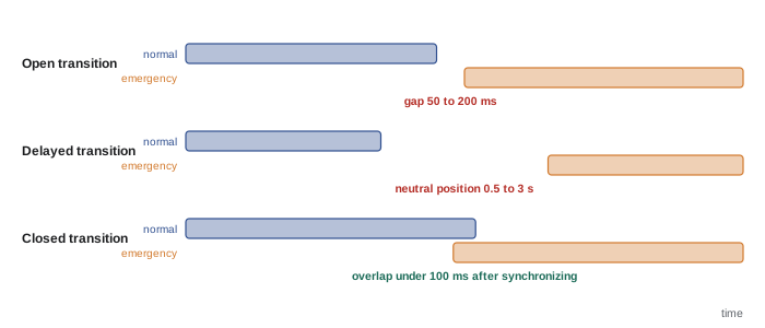
- Open transition (break-before-make): the switch disconnects the load from one source and then connects it to the other, with an interruption of about 50 to 200 ms. This is the usual mode for transfer to the generator, because the utility has already failed.
- Delayed transition: the switch pauses in a center-off (neutral) position for an adjustable time, typically 0.5 to 3 seconds, before connecting the new source. The delay lets the residual voltage of spinning motors and transformer magnetization decay, so that connecting the new source out of phase does not cause high inrush currents and torques.
- Closed transition (make-before-break): when both sources are available, for example when returning to the utility or in a test, the switch synchronizes the generator to the utility and briefly connects both, for less than about 100 ms, before opening the source being released. The load sees no interruption at all, avoiding a second outage on retransfer.
- Soft-load closed transition: the generator and utility stay in parallel for several seconds while the generator's controls ramp the load gradually from one source to the other, avoiding a large step on either. Because the generator is paralleled with the grid for longer, the utility requires interconnection protection and approval.
Bypass-isolation and other features
A bypass-isolation ATS has a second switching mechanism that can carry the load directly from either source while the main transfer mechanism is drawn out for testing or repair, so that maintenance never requires an outage. This feature is common on data center mechanical and house loads fed through ATSs.
Switching the neutral
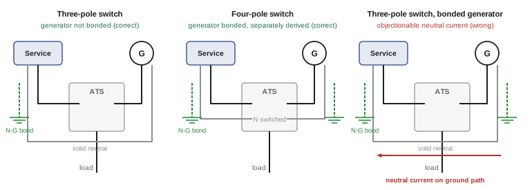
Whether the transfer switch must switch the neutral (four-pole) or not (three-pole) depends on how the generator is grounded. If the generator's neutral is bonded to ground at the generator, making it a separately derived system, the neutral must be switched; otherwise neutral current would return partly through the bonding conductors and the two neutral-to-ground bonds would confuse ground-fault protection. If the generator neutral is solidly connected to the utility service neutral through a three-pole switch, the generator is not separately derived and must not be bonded at the generator. Data centers with ground-fault protection on their main breakers usually use four-pole switching or careful sensor arrangements to avoid nuisance tripping.
Ratings
A transfer switch must carry its continuous current and survive the available fault current until the upstream protective device clears it. Its withstand and closing rating (WCR) is stated either with specific upstream breakers or fuses, or as a time-based rating (for example, 65 kA for 30 cycles) that allows coordination with short-time delayed breakers upstream. Data center designs often need time-based ratings so that the selective coordination studied in DCE-310 is not compromised.
Sequence of operation
A typical automatic sequence for a data center on a utility outage is:
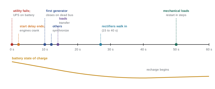
- The utility voltage on any phase falls below its pickup (often 85 to 90% of nominal) or the frequency goes out of limits. The UPSs transfer to battery instantly.
- A short engine-start delay (typically 1 to 3 seconds) avoids starting the generators for a momentary interruption that utility reclosers will clear.
- The generators start. When each reaches rated voltage and frequency (within about 10 seconds), the paralleling controls close the first generator onto the dead bus and synchronize the others.
- The transfer switches or generator main breakers transfer the loads, in a planned sequence, after the utility main breakers have opened.
- The UPS rectifiers walk in onto the generator power over 10 to 30 seconds and begin recharging the batteries; mechanical loads restart in steps.
When the utility returns, the controls wait for a retransfer delay, commonly 5 to 30 minutes, to be sure it is stable, then return the load by closed transition (or open transition, in which case the UPS batteries carry the brief gap). The generators run unloaded for a cool-down period of 5 to 15 minutes before stopping.
Worked problem
How much battery is used?
In an outage, the engine start delay is 2 s, the generators take 9 s to reach rated conditions, synchronizing and closing take 4 s, transfer takes 1 s, and the UPS rectifiers then walk in over 20 s, during which the battery supplies a share of the load that falls linearly from 100% to 0. The battery is sized for 5 minutes at full load. What fraction of its capacity is used, ignoring rate effects?
Show solution
- Full-load battery time before walk-in: \(2 + 9 + 4 + 1 = 16\) s.
- Walk-in: the average share over 20 s is 50%, equivalent to 10 s at full load.
- Total: \(16 + 10 = 26\) s at full load out of 300 s, or 8.7%.
Answer: Under 10% of the capacity. The rest of the 5 minutes covers a failed first start, a slow synchronization, operator intervention and the reduced capacity of an aged battery.
Paralleling generators
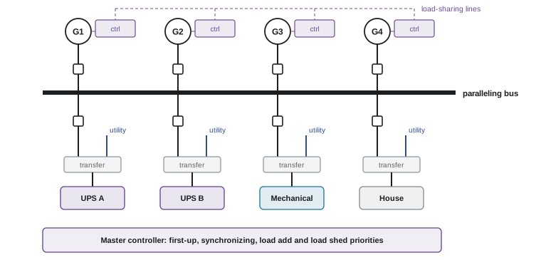
Large facilities connect several generators to a common bus through paralleling switchgear rather than giving each load its own generator. Paralleling allows N+1 redundancy shared across the whole load, the use of standard generator sizes for any load, and maintenance of one generator at a time. The switchgear includes a breaker for each generator, a bus, feeder breakers to the distribution, and controls for synchronizing, load sharing, load add and load shed.
Synchronizing
Before a generator breaker closes onto a live bus, the incoming generator must match the bus in four respects:
- Phase sequence (rotation), checked once at commissioning.
- Voltage magnitude, typically within about 5%.
- Frequency, with a small slip so that the phase angle drifts slowly, typically 0.05 to 0.2 Hz.
- Phase angle, within about ±10° at the instant the contacts close.
Closing out of phase is extremely damaging: at 120° the voltage difference across the breaker approaches twice the system voltage, producing currents larger than a short circuit and torque on the shaft that can crack couplings and crankshafts. An automatic synchronizer adjusts the governor and AVR of the incoming set and issues the close command slightly in advance of zero phase difference, to allow for the breaker's closing time. A synchronism check relay (device 25) independently blocks closing outside the window.
Worked problem
Synchronizing window
An incoming generator runs 0.1 Hz faster than the bus. The permitted phase window is ±10°, and the breaker takes 5 cycles (83 ms at 60 Hz) to close. How long does the phase angle stay within the window on each pass, and how far in advance should the synchronizer issue the close command?
Show solution
- At 0.1 Hz slip, the phase difference changes by \(0.1 \times 360 = 36°\) per second, completing a full cycle every 10 s.
- Time within ±10°: \(20/36 = 0.56\) s per pass.
- Advance angle: \(36° \times 0.083 = 3.0°\). The synchronizer issues the close command when the incoming phase is 3° behind the bus, so that the contacts touch at 0°.
Answer: About 0.56 s in the window every 10 s, with the close issued 3° early. A larger slip shortens the window and increases the advance angle, which is why synchronizers bring the slip down before closing.
First-up and dead-bus closing
After an outage the paralleling bus is dead. The first generator to reach rated voltage and frequency is allowed to close onto the dead bus without synchronizing, and the master controller then blocks all other generators from doing the same, because two generators closing on a dead bus simultaneously could be out of phase. This first-up arbitration is a critical piece of logic, usually implemented with redundant hardware and interlocks. The remaining generators synchronize to the live bus one after another. Some designs close all generator breakers before the engines are excited and build up voltage together ("dead-field" paralleling), getting every set on the bus within a few seconds.
Load sharing
Once paralleled, the generators must share real power (kW) and reactive power (kvar) in proportion to their ratings. Two methods are used:
- Isochronous load sharing: the generator controllers communicate (through analog load-sharing lines or a digital network) and adjust their governors so that all run at exactly 60 Hz while carrying equal per-unit loads. Reactive power is shared by cross-current compensation or communicated voltage control.
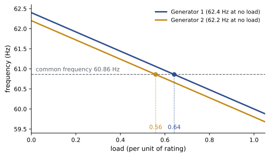
- Droop: each governor reduces its speed setpoint as load rises, for example by 4% from no load to full load. Generators connected together must run at the same frequency, so they settle at a frequency where their loads correspond to that frequency on each droop line. Droop works without communication and is used as a fallback, and when paralleled with the utility.
Worked problem
Droop sharing with mismatched settings
Two identical 2000 kW generators have 4% droop (2.4 Hz from no load to full load). Generator 1 is set to 62.4 Hz at no load and generator 2 to 62.2 Hz. They supply 2400 kW together. Find the frequency and each generator's load.
Show solution
- Each generator's load in per unit: \(P_1 = (62.4 - f)/2.4\) and \(P_2 = (62.2 - f)/2.4\).
- Total: \(P_1 + P_2 = 2400/2000 = 1.2\) per unit, so \((124.6 - 2f)/2.4 = 1.2\), giving \(2f = 124.6 - 2.88 = 121.72\) and \(f = 60.86\) Hz.
- \(P_1 = (62.4 - 60.86)/2.4 = 0.642\) per unit = 1283 kW; \(P_2 = (62.2 - 60.86)/2.4 = 0.558\) per unit = 1117 kW.
Answer: The frequency settles at 60.86 Hz with generator 1 carrying 1283 kW and generator 2 carrying 1117 kW, a 166 kW imbalance from a 0.2 Hz setting difference. Isochronous load sharing removes both the frequency offset and the imbalance.
Load add and load shed
The master controller adds loads to the bus in priority order as generators come online: critical UPS loads first, then the cooling needed to protect them, then non-critical loads. If a generator fails while the plant is running, the remaining capacity may be less than the load, and the controller must shed low-priority loads instantly (within a fraction of a second, often on an under-frequency signal) to prevent the remaining generators from overloading and collapsing one after another. Load shed schemes are tested at commissioning by tripping a generator under load.
Worked problem
Load shed after a generator trip
Five 2.5 MW generators carry 10.8 MW: UPS loads 7.0 MW (priority 1), cooling 3.0 MW (priority 2) and offices and non-critical loads 0.8 MW (priority 3). One generator trips. What must be shed? What if a second one trips?
Show solution
- Four generators: 10.0 MW available against 10.8 MW load. Shedding priority 3 (0.8 MW) leaves 10.0 MW, exactly at capacity, so in practice part of the priority 2 load is also reduced, for example by limiting chiller capacity briefly.
- Three generators: 7.5 MW available. Priority 1 alone is 7.0 MW, leaving only 0.5 MW for cooling, which cannot sustain the IT load for long.
Answer: One trip: shed non-critical loads and trim cooling. Two trips: the plant cannot support the facility, which is why the plant is designed at least N+1 and why cooling is ranked just behind the UPS load rather than with non-critical loads.
Medium-voltage paralleling
On large campuses, generators are increasingly connected at medium voltage, either as MV generators (for example 13.8 kV) or LV generators with step-up transformers, onto an MV paralleling bus that feeds the substations. MV paralleling reduces currents, cable sizes and switchgear count, and allows generator plants of 50 MW or more to back up an entire building. It also introduces MV protection, transformer energization inrush and longer sequences that must still fit within the UPS battery runtime.
Paralleling with the utility
Closed-transition transfer, soft loading, load bank testing on the utility bus and peak shaving all require generators to operate in parallel with the grid, if only briefly. Utilities require protection that prevents the generator from back-feeding or destabilizing their network: synchronism check, reverse power (device 32), under- and over-voltage and frequency relays, and limits on the time spent in parallel (often 100 ms for closed transition without further study).
In the US, interconnection follows IEEE 1547 and each utility's interconnection rules and agreements, often administered under state public utility commission tariffs; even momentary paralleling for closed transition usually needs the utility's written approval.
Lesson 8 covers the protection studies that must account for each source and transfer state, and Lesson 10 how transfer sequences are proven during commissioning.
Common mistakes
MistakeUsing a three-pole ATS with a generator that is bonded at the generator.
InsteadSwitch the neutral (four-pole) for separately derived generators, or do not bond at the generator.
MistakeTransferring large motor loads with a fast open transition.
InsteadUse delayed transition (or closed transition) so that residual voltage decays.
MistakeClosing a generator breaker with a large slip frequency.
InsteadReduce the slip, issue the close in advance of 0°, and use a synch check relay.
MistakeOmitting first-up arbitration.
InsteadAllow only one generator to close on a dead bus; others must synchronize.
MistakeParalleling with the utility without approval or protection.
InsteadObtain the utility's approval and install the required relaying, even for closed transition.
Summary and key terms
- ATSs (UL 1008) or breaker pairs transfer loads between utility and generator.
- Open, delayed and closed transitions trade interruption against complexity and utility approval.
- Bypass-isolation ATSs allow maintenance without an outage.
- Four-pole switching is needed when the generator is a separately derived system.
- Withstand and closing ratings must suit the fault current and coordination scheme.
- Outage sequence: detect, delay, start, close first-up, synchronize, transfer, walk in; retransfer after a stability delay.
- Synchronizing requires matching rotation, voltage, frequency (small slip) and phase (within about ±10°).
- Generators share load isochronously with communication, or by droop.
- Load add and shed by priority keep the plant stable after a generator failure.
- Paralleling with the grid requires utility approval and protection (IEEE 1547).
- ATS
- Automatic transfer switch.
- Open transition
- Break-before-make transfer with a brief interruption.
- Delayed transition
- Transfer with a pause in a neutral position to let residual voltage decay.
- Closed transition
- Make-before-break transfer with a brief overlap of synchronized sources.
- Bypass-isolation switch
- An ATS with a bypass that carries the load while the main mechanism is withdrawn.
- Separately derived system
- A source whose neutral is not solidly connected to another system's neutral.
- WCR
- Withstand and closing rating of a transfer switch.
- Paralleling switchgear
- Switchgear that connects multiple generators to a common bus.
- Slip frequency
- The frequency difference between an incoming generator and the bus.
- Synchronism check relay
- A relay (device 25) that permits closing only within voltage, frequency and angle limits.
- First-up
- The generator allowed to close onto a dead bus.
- Isochronous load sharing
- Sharing load at constant frequency by communication between controllers.
- Droop
- A governor characteristic in which frequency falls as load rises.
- Load shed
- Automatic disconnection of low-priority loads to protect generator capacity.
Practice problems
Work each problem on paper first, then reveal the answer to check.
Why does an ATS usually transfer to the generator by open transition?
Show answer
The utility has already failed, so there is nothing to synchronize with; the UPS carries the critical load through the gap.
What problem does delayed transition solve?
Show answer
Residual voltage of motors and transformers being out of phase with the new source, causing inrush and torque.
When must a transfer switch switch the neutral?
Show answer
When the generator neutral is bonded to ground at the generator (separately derived system).
The engine start delay is 3 s, generators take 10 s, synchronizing 5 s, transfer 1 s, walk-in 30 s. Equivalent full-load battery seconds?
Show answer
3 + 10 + 5 + 1 + 15 = 34 s.
Why is a retransfer delay of several minutes used when the utility returns?
Show answer
To ensure the utility is stable and avoid transferring back into a second outage.
At 0.2 Hz slip, how long is the phase angle within ±10° each pass?
Show answer
Phase changes 72°/s; 20/72 = 0.28 s.
With 0.2 Hz slip and a 100 ms breaker closing time, what is the advance angle?
Show answer
72 × 0.1 = 7.2°.
Two identical generators with 5% droop (3 Hz) are set to 63.0 and 62.7 Hz at no load and share 1.0 per unit total. Find the frequency.
Show answer
(125.7 − 2f)/3 = 1.0 → f = 61.35 Hz; P1 = 0.55, P2 = 0.45 per unit.
Why must only one generator close on a dead bus?
Show answer
Two generators closing simultaneously could be out of phase, causing massive current and torque.
Name two relays a utility might require for closed transition or paralleling.
Show answer
Synchronism check (25), reverse power (32), under/over voltage (27/59), under/over frequency (81).
Lesson quiz · 5 questions
Score 60% or more to complete this lesson.
Create a free account to save your progress, take quizzes and earn a certificate.