
DCE-340 · Lesson 12 of 12 · 28 min
Designing a backup power system
The earlier lessons treated each part of backup power separately: UPS topologies, the utility supply, batteries, DC and rack-level storage, generators, BESS and on-site generation, transfer and paralleling, protection, redundancy architectures, testing and operations. This final lesson combines them in a design project for a new data hall that mixes AI training racks with conventional IT, following the sequence a design team would use: requirements, load and growth, architecture, sizing of each component, protection and controls, reliability assessment, sustainability, and the plan for testing and operations.
Step 1: Requirements
The owner's requirements set the design targets:
- IT load: 24 MW at full build, in four phases of 6 MW. Of this, 16 MW is AI training (liquid-cooled racks of 130 kW with fast power swings) and 8 MW conventional IT.
- Availability: concurrently maintainable throughout (every component can be maintained without dropping load), with fault tolerance on the conventional IT through dual-corded 2N distribution; AI training racks accept N+1 redundancy with single-corded racks, because training jobs checkpoint and can restart.
- Utility: two 138 kV transmission lines to an on-site substation, with a five-year wait for additional capacity, so phased growth must fit within the first allocation.
- Sustainability: minimize diesel run hours, use renewable diesel (HVO) where permitted, and support grid flexibility programs.
- Site: cold continental climate (winter design −30 °C), air permit limits on generator run hours for testing.
Separating AI and conventional loads by their real needs avoids applying the most expensive redundancy everywhere, a common source of over-design.
Step 2: Loads and growth
The design load includes more than IT. Cooling, controls and other mechanical loads must also be backed up, at least partly, because IT cannot run long without cooling (DCE-330):
Worked problem
Total backed-up load
At full build, IT is 24 MW. Mechanical loads that must run during an outage (CDU pumps, fans, chillers on the hottest day) peak at 25% of IT load, and other critical loads (controls, lighting, security) at 2%. What generator capacity is needed before redundancy?
Show solution
- Mechanical: \(0.25 \times 24 = 6.0\) MW; other: \(0.02 \times 24 = 0.48\) MW.
- Total: \(24 + 6.0 + 0.48 = 30.5\) MW, at a power factor of about 0.95 for modern loads.
Answer: About 30.5 MW (32 MVA), the basis for generator sizing. The UPS supports the IT load and the critical part of mechanical load (pumps and fans that must not stop), while chillers can restart on generator power (DCE-330, Lesson 11).
Growth is phased: equipment is installed in 6 MW blocks, with the electrical rooms, generator yard, fuel storage and medium-voltage switchgear laid out for the full 24 MW from the start.
Step 3: Architecture
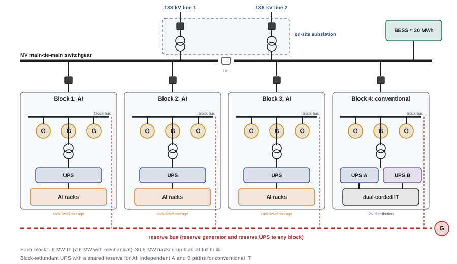
The team chooses a block-redundant architecture for the AI zone and a distributed-redundant (or 2N) arrangement for conventional IT (Lesson 9):
- Medium-voltage (34.5 kV or 13.8 kV) distribution from the on-site substation in a main-tie-main arrangement (Lesson 2).
- For each 6 MW block: medium-voltage generators paralleled on a block bus, with one reserve generator shared across blocks through a reserve bus (catcher).
- UPS: for the AI zone, 1.5 MW to 2 MW UPS systems in a block-redundant configuration with a reserve UPS that picks up any block's load through static transfer; for conventional IT, two independent UPS paths (A and B) feeding dual-corded equipment.
- Rack-level energy storage in the AI racks to smooth power swings (Lesson 4), coordinated with UPS and generator controls.
- A BESS of about 20 MWh at the substation for peak shaving, grid services and, in an outage, to bridge generator starts and carry the load through short outages, reducing generator runs (Lesson 6).
Step 4: Sizing
Generators
With 30.5 MW at full build, 3 MW medium-voltage generators give 11 units for N (33 MW). In the block-redundant arrangement, each 6 MW block (with its mechanical share, about 7.6 MW) needs three running generators (9 MW), and one reserve generator per four blocks provides redundancy; alternatively, N+1 per block. The team compares: block-redundant with a shared reserve needs 13 generators; N+1 per block needs 16.
Each generator must also accept the block loads expected in a transfer (Lesson 10): UPS rectifiers walk in over 10 to 20 seconds, and CDU pumps and fans start in stages. AI load swings require generators and controls tested against the power profile, with rack-level storage reducing the swings the generators see.
Worked problem
Fuel storage
Generators consume about 0.27 L/kWh at their load. The owner requires 48 hours of on-site fuel at the full backed-up load of 30.5 MW. How much fuel is stored?
Show solution
- Energy: \(30.5 \times 48 = 1{,}464\) MWh.
- Fuel: \(1{,}464{,}000 \times 0.27 = 395{,}000\) L.
Answer: About 395,000 L (roughly 104,000 US gallons), in several tanks for redundancy and maintenance, with fuel polishing, monitoring and delivery contracts for longer outages (Lesson 5 and Lesson 11).
UPS and batteries
UPS runtime is chosen to cover generator start, synchronization and transfer with margin, plus retries: 5 minutes at full load is common with lithium-ion batteries. The BESS adds a second layer, allowing the UPS batteries to be sized for bridging only.
Utility capacity
The 138 kV allocation must cover the peak grid draw. Because the BESS can shave peaks, and AI training workloads can be throttled during grid emergencies by agreement, the facility may fit a lower allocation than its full nameplate, an important advantage where new transmission capacity takes years.
Step 5: Protection and controls
- Short-circuit, coordination and arc flash studies for every operating mode: utility, BESS-islanded, generator, reserve-bus transfers, and UPS on battery (Lesson 8).
- Excitation support on generators; protective setting groups that change with the source.
- Paralleling controls with redundant PLCs, dead-bus closing, load add and shed, and coordination with the BESS and UPS (Lesson 7).
- Ride-through settings agreed with the grid operator, so that the facility stays connected through normally cleared transmission faults and returns to the grid in steps after an outage (Lesson 2).
- An energy management system that coordinates BESS dispatch, grid programs and the backup reserve, never reducing the reserve below the backup requirement.
Step 6: Reliability assessment
The design is assessed quantitatively for its weakest points. A reliability block diagram or simulation (Lesson 9) estimates the probability that each block loses power in a year, considering utility outages, generator start and running failures, UPS failures, and common-mode risks.
import numpy as np

rng = np.random.default_rng(21)
years = 200000
outages = rng.poisson(1.5, years)                    # utility outages per year

def lost_load_years(n_needed, n_installed, p_fail_start, p_fail_run_hr, mean_hours):
    lost = 0
    for k in outages[outages > 0]:
        for _ in range(k):
            hours = rng.lognormal(np.log(mean_hours), 1.0)
            started = rng.random(n_installed) > p_fail_start
            # each running unit may also fail during the outage
            survived = started & (rng.random(n_installed) > 1 - np.exp(-p_fail_run_hr * hours))
            if survived.sum() < n_needed:
                lost += 1
                break
    return lost / years

designs = [("N (6 of 6)", 6, 6), ("N+1 (6 of 7)", 6, 7), ("N+2 (6 of 8)", 6, 8)]
for name, need, inst in designs:
    p = lost_load_years(need, inst, p_fail_start=0.005, p_fail_run_hr=0.0005, mean_hours=1.0)
print(f"{name:13s}: probability of losing load in a year {p:.1e} (about once in {1 / p if p else float(1e9):,.0f} years)")N (6 of 6) : probability of losing load in a year 5.0e-02 (about once in 20 years) N+1 (6 of 7) : probability of losing load in a year 1.1e-03 (about once in 893 years) N+2 (6 of 8) : probability of losing load in a year 1.5e-05 (about once in 66,667 years)
The simulation shows how strongly redundancy reduces the chance of losing load when failures are independent, and therefore why common-mode failures, which break independence, dominate real risk: a shared fuel problem, a control fault affecting all generators, or a breaker that trips on generator power. The design review therefore focuses on removing common modes (separate fuel tanks, independent control networks, tested settings) as much as on counting units.
Step 7: Sustainability
- Diesel runtime: the BESS carries short outages and monthly tests are reduced to the minimum permitted, cutting generator run hours.
- Fuel: renewable diesel (HVO), which works in standard diesel engines and cuts lifecycle emissions, where available and allowed by the engine manufacturer.
- Emissions: generators meeting the applicable emission tiers, with after-treatment where required by the air permit.
- Grid support: participation in demand response and fast frequency response with the BESS and, where agreed, flexible AI workloads.
- Embodied carbon: fewer generators through block redundancy and battery-based bridging reduces material and manufacturing emissions.
Step 8: Testing and operations plan
The design includes provisions that make testing and operation possible (Lessons 10 and 11):
- Load bank connections at each block bus and liquid load bank connections for AI CDU loops.
- Factory witness tests for generators, UPS, switchgear and paralleling controls; integrated systems testing of each block before it carries customer load, and again after each phase is added.
- Monitoring of every UPS, battery string, generator and breaker, with capacity alarms that warn before redundancy is lost.
- MOPs, EOPs and operator training for each mode of operation, including manual paralleling and BESS islanding.
Worked problem
Phase additions and redundancy
Phase 2 adds a second 6 MW block. During its construction, its generators are connected to the reserve bus for testing. What risk does this create for phase 1, and how is it managed?
Show solution
- While the reserve bus is used for testing, phase 1 has no reserve generator: its redundancy is reduced.
- A fault during testing on the reserve bus could also disturb phase 1 if interlocks are wrong.
Answer: Schedule reserve-bus testing in short, planned windows under a MOP, with phase 1 temporarily supported by its own N+1 or by the BESS, and verify interlocks before any connection. Construction of later phases next to live phases is one of the riskiest periods in a data center's life.
Every step drew on earlier lessons: the supply and its disturbances, UPS and batteries, DC and rack storage, generators and fuel, BESS and grid services, transfer and paralleling, protection, redundancy, testing and operations. Designing backup power is the art of combining them so that the IT load stays up through whatever the grid, the equipment and people do.
Common mistakes
MistakeApplying the highest redundancy to every load.
InsteadMatch redundancy to each load's real needs, such as N+1 for checkpointing AI training and 2N for critical dual-corded IT.
MistakeSizing generators for IT load only.
InsteadInclude mechanical and other critical loads and the transfer step loads.
MistakeCounting redundant units without checking common modes.
InsteadRemove shared fuel, control and protection dependencies.
MistakeLetting grid services eat into the backup reserve.
InsteadEnforce the reserve in the energy management controls.
MistakeIgnoring construction risk when adding phases.
InsteadPlan reserve-bus use, interlocks and MOPs for work beside live phases.
Summary and key terms
- Start from requirements: load, growth, availability per load type, utility, sustainability and site.
- Backed-up load includes mechanical and critical loads, not just IT.
- Block-redundant AI zones and 2N conventional zones can share reserve generators and a BESS.
- Size generators, fuel, UPS runtime and utility capacity together, with storage reducing each.
- Protection, controls and ride-through are designed for every mode; reliability analysis targets common modes.
- Sustainability, testing provisions and operations plans are part of the design from the start.
- Design load
- The load the backup system must carry, including growth.
- Phased build
- Installing capacity in blocks as demand grows.
- Reserve bus
- A bus allowing a reserve generator or UPS to supply any block.
- Block-redundant
- An architecture where a shared reserve covers several blocks.
- HVO
- Hydrotreated vegetable oil, a renewable diesel fuel.
- Energy management system
- Controls coordinating storage, generation and grid programs.
- Monte Carlo simulation
- Estimating probabilities by simulating many random scenarios.
- Common-mode risk
- A single cause that can defeat redundant components.
- Utility allocation
- The capacity the utility agrees to supply.
- Integrated systems test
- A whole-facility test under load and induced failures.
Practice problems
Work each problem on paper first, then reveal the answer to check.
Backed-up load for 10 MW IT with mechanical 30% and other 2%?
Show answer
13.2 MW.
Generators of 2.5 MW for 13.2 MW at N+1?
Show answer
6 + 1 = 7.
Fuel for 13.2 MW for 24 h at 0.27 L/kWh?
Show answer
About 85,500 L.
Why can AI training accept N+1 rather than 2N?
Show answer
Jobs checkpoint and can restart after an interruption.
What does a BESS add to the backup design?
Show answer
Bridging, short-outage ride-through, peak shaving and grid services.
Why include mechanical loads in generator sizing?
Show answer
IT cannot run long without cooling.
Why do common modes dominate real risk?
Show answer
They defeat the independence that redundancy relies on.
Name two ways to reduce diesel use.
Show answer
BESS for short outages, renewable diesel, minimal testing.
What risk arises when later phases are tested on the reserve bus?
Show answer
Live phases temporarily lose their reserve.
What studies cover protection across modes?
Show answer
Short-circuit, coordination and arc flash studies.
Lesson quiz · 5 questions
Score 60% or more to complete this lesson.
Create a free account to save your progress, take quizzes and earn a certificate.