
DCE-340 · Lesson 4 of 12 · 28 min
DC power and rack-level energy storage
The classic data center power chain converts electricity many times: AC from the utility to DC in the UPS rectifier, back to AC in the inverter, then to DC again in each server's power supply, and finally down to the low voltages that processors use. Every conversion wastes a few percent and adds equipment that can fail. Telecommunications offices have long used DC power, and hyperscale operators and AI system builders have moved much of the conversion and energy storage into the rack, at 48 V and, for the newest AI racks, at 400 V or 800 V DC. This lesson explains telecom −48 V plants, 380/400 V DC distribution, rack-level power shelves and battery backup units, energy storage that smooths AI power swings, and the efficiency, safety and protection issues of DC.
Why the number of conversions matters
Each conversion stage has an efficiency, and the overall efficiency is their product. A chain of five stages at 96% to 99% each loses 15% to 20% of the energy between the utility and the chips, all of which becomes heat that must be removed. Removing stages, or making each more efficient, saves both electricity and cooling.
# Delivering 120 kW to one AI rack: current, conductor loss and conversion chain at different voltages
rack_kw = 120.0
run_m = 2.0                        # busbar or cable length inside the rack, each way
r_per_m = 0.00005                  # ohm per metre of a heavy copper busbar (same bar at every voltage)

for v in (12.0, 48.0, 400.0, 800.0):
    i = rack_kw * 1000 / v
    loss = i ** 2 * (2 * run_m * r_per_m)
    print(f"{v:5.0f} V DC: current {i:7.0f} A, busbar loss {loss / 1000:6.2f} kW ({100 * loss / (rack_kw * 1000):5.2f}%)")

# Conversion chains, end to end efficiency from medium-voltage AC to the processor rails
chains = {
    "AC UPS, 415 V AC to rack, PSU to 12 V": [0.985, 0.96, 0.995, 0.945, 0.92],
    "AC UPS bypassed (eco mode), 48 V rack": [0.985, 0.99, 0.995, 0.97, 0.94],
    "800 V DC from solid-state transformer": [0.98, 0.995, 0.975, 0.95],
}
for name, effs in chains.items():
    total = 1.0
    for e in effs:
        total *= e
print(f"{name:40s}: {100 * total:5.1f}% overall, losses {rack_kw * (1 / total - 1):5.1f} kW per 120 kW rack")12 V DC: current 10000 A, busbar loss 20.00 kW (16.67%) 48 V DC: current 2500 A, busbar loss 1.25 kW ( 1.04%) 400 V DC: current 300 A, busbar loss 0.02 kW ( 0.01%) 800 V DC: current 150 A, busbar loss 0.00 kW ( 0.00%) AC UPS, 415 V AC to rack, PSU to 12 V : 81.8% overall, losses 26.7 kW per 120 kW rack AC UPS bypassed (eco mode), 48 V rack : 88.5% overall, losses 15.6 kW per 120 kW rack 800 V DC from solid-state transformer : 90.3% overall, losses 12.9 kW per 120 kW rack
Two lessons stand out. First, current falls in proportion to voltage and resistive loss with its square: delivering 120 kW at 12 V would need 10,000 A and lose a sixth of the power in the busbar, which is why racks moved from 12 V to 48 V, and why the densest AI racks are moving to hundreds of volts. Second, the conversion chain dominates losses; the assumed stage efficiencies show the scale of improvement possible by removing or improving stages, though real values depend on equipment and load.
Telecom −48 V DC plants
Telephone central offices and many network facilities run their equipment from a −48 V DC plant: rectifiers convert AC to DC and float-charge large battery strings connected directly to the DC bus, which feeds equipment through fused distribution panels. When the AC supply fails, the batteries continue to supply the bus with no transfer at all, the simplest possible UPS. The positive terminal is grounded, a convention from early telephony that reduces corrosion of outside cables. DCE-210 introduced these plants; for data centers, their lessons are the reliability of batteries directly on a DC bus and the cost of low voltage: high currents need very large conductors and careful voltage-drop design.
Worked problem
Voltage drop at −48 V
A −48 V distribution feeds a 6 kW equipment rack 30 m from the battery plant. The equipment works down to −42 V, and the batteries end their discharge at −44 V. With copper cable of 2 × 120 mm² (0.000154 Ω/m per conductor), is the drop acceptable at end of discharge?
Show solution
- Current at 44 V: \(6{,}000/44 = 136\) A.
- Loop resistance: \(2 \times 30 \times 0.000154 = 0.00924\) Ω.
- Drop: \(136 \times 0.00924 = 1.26\) V; equipment sees \(44 - 1.26 = 42.7\) V.
Answer: Just acceptable at 42.7 V. The same rack at 400 V DC would need about 15 A, and a much smaller cable with negligible drop.
380/400 V DC data centers
Distributing DC at around 380 V to 400 V (standardized, for example, in ETSI EN 300 132-3 and by industry groups) removes the UPS inverter and the server power supply's rectification stage: a central rectifier with batteries on its DC bus feeds racks, whose power supplies convert 380 V DC directly to the board voltages. Demonstrations reported efficiency gains of several percent and fewer components. Adoption was slowed by the lack of standard equipment, breakers and connectors, and by the need for staff trained in DC safety. Interest has revived for AI racks, where power per rack makes high-voltage distribution almost unavoidable.
Protecting and switching DC
DC is harder to interrupt than AC: AC current passes through zero 100 or 120 times a second, helping an arc extinguish, while DC current has no zero crossing. DC breakers, fuses and switches therefore need ratings specifically for DC voltage and current, with arc chutes, magnetic blowout or solid-state interruption. Connectors must be designed so that they cannot be unplugged under load or must interrupt arcs safely. Ground-fault detection on ungrounded or resistance-grounded DC systems requires insulation monitoring devices.
Rack-level power: shelves and battery backup units
Hyperscale operators, through the Open Compute Project (OCP) and in their own designs, moved power conversion into the rack. In the Open Rack design, a power shelf of rectifier modules converts AC (or high-voltage DC) to a rack busbar, originally at 12 V and now at 48 V (Open Rack V3), and servers draw from the busbar with simple connectors, without individual power supplies. Battery backup units (BBUs), modules of lithium-ion cells in the power shelf, connect to the busbar and supply the rack for a few minutes when the input fails.
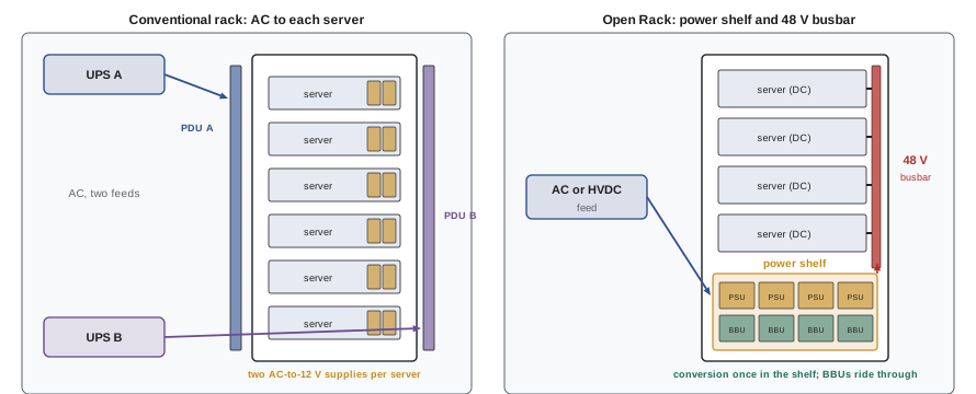
Moving the battery to the rack has advantages:
- It removes the central UPS and its double conversion for those racks, improving efficiency, especially when combined with eco-mode or bypass at the facility level.
- Battery capacity scales with racks as they are added.
- A battery failure affects one rack, not a whole hall.
It also has costs: thousands of small batteries to monitor and replace, lithium-ion fire risk distributed through the white space (Lesson 3), and runtimes of only a few minutes, so generators must start and accept load quickly. Many operators combine BBUs with facility-level generators and no central UPS.
Worked problem
Sizing a BBU shelf
A 48 V rack draws 33 kW. Its BBUs must support it for 4 minutes, with 90% conversion efficiency from battery to busbar and 80% usable capacity at end of life. How much nominal battery energy is needed?
Show solution
- Energy to the load: \(33 \times 4/60 = 2.2\) kWh.
- From the battery: \(2.2/0.9 = 2.44\) kWh.
- At 80% end-of-life capacity: \(2.44/0.8 = 3.06\) kWh nominal.
Answer: About 3.1 kWh of nominal battery energy, a few BBU modules. Short runtime keeps the batteries small, but the discharge rate is high (more than 10 times the capacity per hour), so the cells must be designed for high power.
High-voltage DC for AI racks
AI racks with 100 kW to several hundred kilowatts strain 48 V distribution: at 48 V, a 240 kW rack needs 5,000 A. Industry designs have therefore moved toward higher DC voltages delivered to the rack:
- Designs presented through OCP use around ±400 V DC to the rack, with a separate power rack ("sidecar") containing AC-to-DC conversion and energy storage beside the compute racks.
- Accelerator vendors have announced 800 V DC architectures for future AI facilities, with solid-state transformers converting medium-voltage AC directly to 800 V DC and DC-to-DC converters in the racks.
These architectures promise fewer conversion stages, less copper and higher efficiency, but they require new protection, connectors, safety practices and standards, which are still developing.
Energy storage for power smoothing
Synchronized AI training creates fast power swings: thousands of accelerators move together between computation and communication, so a cluster's power can swing by tens of percent in a fraction of a second. These swings stress upstream equipment: generators may struggle to follow them, UPS systems see repeated step loads, and the utility may see oscillations (Lesson 2). Energy storage close to the load smooths them:
- Capacitors and batteries in rack power shelves supply the fast peaks and absorb the dips, so the facility sees a smoother average.
- Software and firmware controls ramp power gradually at the start and end of jobs and limit the rate of change.
- Facility-level battery systems with fast inverters provide a further buffer (Lesson 6).
Worked problem
Storage for smoothing
A rack alternates between 130 kW for 2 s and 70 kW for 2 s. If storage in the rack lets the input draw a constant 100 kW, how much energy must the storage supply and absorb each cycle?
Show solution
- During the high phase the storage supplies \(130 - 100 = 30\) kW for 2 s: 60 kJ.
- During the low phase it absorbs \(100 - 70 = 30\) kW for 2 s: 60 kJ.
- 60 kJ is about 0.017 kWh.
Answer: About 60 kJ (0.017 kWh) per swing, small in energy but cycled every few seconds, millions of times a year. Supercapacitors or high-power cells suit this duty better than ordinary UPS batteries.
Safety with DC systems
DC systems bring specific hazards:
- Arc flash: DC arcs can be sustained at lower voltages than AC arcs and are harder to extinguish; incident energy calculations for DC differ from AC methods, and arc-rated PPE is chosen accordingly (CSA Z462 and NFPA 70E include DC methods).
- Battery energy: batteries cannot be switched off; their terminals are live during maintenance and can deliver very high fault currents.
- Capacitors: DC buses have large capacitor banks that stay charged after disconnection and must be discharged and verified before work.
- Shock: 400 V and 800 V DC are lethal; 48 V is classed as safety extra-low voltage in many contexts but can still cause burns and arcs at high currents.
Lockout procedures for DC systems include isolating rectifiers and batteries, verifying absence of voltage on each conductor, and discharging stored energy.
Common mistakes
MistakeIgnoring conversion losses when comparing architectures.
InsteadMultiply stage efficiencies and compare total losses and cooling.
MistakeUsing AC-rated breakers and switches on DC.
InsteadUse devices rated for the DC voltage and current.
MistakeUnderestimating voltage drop on low-voltage DC distribution.
InsteadSize conductors for drop at end-of-discharge voltage.
MistakeAssuming rack batteries remove the need for fast generators.
InsteadMinutes of BBU runtime require generators to start and load quickly.
MistakeTreating DC systems as dead after switching off rectifiers.
InsteadBatteries and capacitors remain energized; isolate, verify and discharge.
Summary and key terms
- Each conversion costs efficiency; removing stages saves energy and cooling.
- Telecom −48 V plants place batteries directly on the DC bus, at the cost of high currents.
- 380/400 V DC distribution removes inverter and rectifier stages; DC protection needs special devices.
- Open Rack power shelves feed 48 V busbars, with battery backup units in the rack.
- AI racks are moving to ±400 V and 800 V DC, and use local storage to smooth power swings.
- DC arc flash, live batteries and charged capacitors require specific safety practices.
- Conversion stage
- A step converting electricity between AC and DC or between voltages.
- −48 V plant
- A telecom DC power system with positive-grounded 48 V batteries.
- 380 V DC
- A high-voltage DC distribution standard for data centers.
- Power shelf
- A rack unit of rectifier modules feeding a rack busbar.
- Busbar
- A rigid conductor distributing power along a rack.
- BBU
- Battery backup unit in a rack power shelf.
- Open Rack
- An OCP rack standard with centralized rack power.
- Solid-state transformer
- A power-electronic converter replacing a conventional transformer.
- Power smoothing
- Using storage and controls to reduce load fluctuations.
- Insulation monitoring device
- A device detecting ground faults on ungrounded systems.
Practice problems
Work each problem on paper first, then reveal the answer to check.
Overall efficiency of stages 0.98, 0.96, 0.95 and 0.92?
Show answer
About 82.2%.
Current for 60 kW at 48 V and at 400 V?
Show answer
1,250 A and 150 A.
By what factor does loss fall when voltage rises from 48 V to 400 V with the same conductor?
Show answer
(400/48)² ≈ 69.
Why is the positive terminal grounded in telecom plants?
Show answer
To reduce corrosion of outside cables.
Why is DC harder to interrupt than AC?
Show answer
There is no current zero crossing.
Where are BBUs located in Open Rack designs?
Show answer
In the rack power shelf.
Nominal energy for 20 kW for 3 min, 90% efficiency, 80% end-of-life capacity?
Show answer
1.0/0.9/0.8 ≈ 1.39 kWh.
Why do AI racks move beyond 48 V?
Show answer
Currents of thousands of amperes at 48 V are impractical.
Energy per swing to smooth ±40 kW for 1 s each way?
Show answer
40 kJ.
Name two stored-energy hazards in DC systems.
Show answer
Batteries and charged capacitors.
Lesson quiz · 5 questions
Score 60% or more to complete this lesson.
Create a free account to save your progress, take quizzes and earn a certificate.