
DCE-310 · Lesson 7 of 12 · 33 min
Short circuit, coordination and arc flash
Most of the time, a data center's electrical system carries steady, predictable load. The equipment that protects it, however, is designed for the rare moments when something goes badly wrong: a cable insulation failure, a dropped tool across busbars, a failed component inside a UPS. In those moments currents of tens of thousands of amperes can flow, enough to melt copper, burst enclosures and, if a person is nearby, cause fatal burns. Three linked studies make sure the system survives such events: the short-circuit study (how much current can flow), the coordination study (which device opens to clear it) and the arc flash study (how much energy a worker could be exposed to).
These studies are required for every data center and repeated whenever the system changes. This chapter explains what each one calculates, the simplified methods used for estimates, and how designers reduce fault and arc flash hazards without giving up reliability.
Short-circuit current
A short circuit is an unintended low-impedance path between conductors (a bolted three-phase fault, a line-to-line fault) or between a conductor and ground (a ground fault, the most common type). The current is limited only by the impedance of the sources and of the conductors between the source and the fault. The three-phase bolted fault usually gives the highest current, so it is used to check equipment ratings:
where \(Z_{\text{total}}\) is the per-phase impedance from the source to the fault. To calculate it, every impedance is converted to ohms at the same voltage (or to "per-unit" values on a common base), and the impedances in series are added:
- Utility source: from the available fault level at the service, \(Z_s = V^2/S_{\text{SC}}\).
- Transformer: \(Z_t = (V^2/S_{\text{rated}}) \times Z_{\text{pu}}\).
- Cables and busway: resistance and reactance per unit length from tables, times length, divided by the number of parallel sets.
Strictly, impedances add as complex numbers (resistance and reactance separately). Adding magnitudes gives a slightly lower current, which is acceptable for estimates; engineering software does the full calculation.
Worked problem
Fault current at a switchboard and at the end of a feeder
A 2500 kVA, 480 V transformer has 5.75% impedance. (a) Find its impedance in ohms and the fault current at its terminals, assuming an infinite source. (b) A feeder with an impedance of 0.004 Ω per phase runs to a distribution board. Estimate the fault current there. (c) Repeat (a) with a utility source of 500 MVA fault level.
Show solution
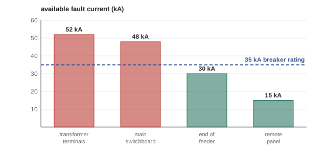
- (a) \(Z_t = (0.48^2/2.5) \times 0.0575 = 0.00530\) Ω (using kV and MVA). \(I_{\text{SC}} = 480/(1.732 \times 0.00530) = 52{,}300\) A.
- (b) \(Z = 0.00530 + 0.004 = 0.00930\) Ω. \(I_{\text{SC}} = 480/(1.732 \times 0.00930) = 29{,}800\) A.
- (c) \(Z_s = 0.48^2/500 = 0.00046\) Ω. \(I_{\text{SC}} = 480/(1.732 \times (0.00046 + 0.00530)) = 48{,}100\) A.
Answer: About 52 kA at the transformer with an infinite source, 48 kA with a realistic utility source, and about 30 kA at the end of the feeder. Fault current falls quickly with distance, so equipment far from the transformer can often have lower interrupting ratings.
Other sources of fault current
The utility and transformers are not the only contributors. Running motors (chillers, pumps, fans) briefly act as generators during a fault and add current, typically several times their full-load current for a few cycles. Generators contribute far less than the utility: a generator's subtransient reactance is typically 10 to 20%, so a 2500 kVA generator delivers only about 5 to 10 times its rated current, and that decays within cycles. UPS inverters contribute least of all, often only 1.5 to 3 times rated current for a short time, because their electronics limit current to protect themselves. This creates a design challenge: a system protected for the high fault current of the utility must also clear faults reliably when running on generators or UPS, where fault currents are much lower and breakers may trip more slowly.
Equipment ratings
Every overcurrent device must have an interrupting rating at least equal to the fault current available at its terminals, and every assembly (switchboard, panelboard, busway, industrial control panel) must have a short-circuit current rating (SCCR) at least equal to the available fault current. A breaker asked to interrupt more than its rating can fail violently. Codes require the available fault current to be determined and, for service equipment, marked on the equipment, so that inspectors and future modifications can check ratings. A related technique, series rating, allows a downstream breaker with a lower rating to be used behind an upstream current-limiting device, but only in tested and listed combinations.
Coordination
When a fault occurs, the ideal is that only the protective device immediately upstream of the fault opens, and everything else stays on. This is selective coordination. If a fault on one rack circuit trips the main breaker of the whole critical switchboard, a small problem has become a large outage, which in a data center can mean thousands of servers going down for a failure that should have affected one rack.
Coordination is studied on time-current curves (TCCs), log-log plots of each device's operating time against current. For two devices in series to coordinate, the downstream device's curve must lie entirely below and to the left of the upstream device's curve, for every current up to the available fault current at the downstream device. Coordination is achieved by choosing device sizes and trip settings: long-time pickup and delay, short-time pickup and delay (which lets a large breaker wait for a smaller one to clear), and instantaneous settings.
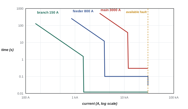
The difficulty is at high currents, where all breakers trip instantaneously and their curves tend to merge. Designers solve this with breakers that have short-time withstand ratings (LV power circuit breakers can hold a fault for up to 30 cycles), carefully chosen instantaneous settings, current-limiting fuses with published selectivity ratios, and manufacturer-tested selectivity tables. Zone-selective interlocking (ZSI) adds communication: a downstream breaker that sees a fault tells the upstream breaker to wait; if the upstream breaker receives no such signal, the fault must be in its own zone and it trips without delay.
The NEC requires selective coordination for emergency systems (Article 700) and legally required standby systems (Article 701), among others. For the critical IT load of a data center, which is usually an optional standby system, it is normally an owner's requirement written into the design criteria, because the cost of an unnecessary outage is so high.
Worked problem
Checking coordination
A feeder breaker has a short-time pickup of 4000 A with a 0.3 s delay. A downstream breaker clears faults above 2000 A in 0.05 s. The available fault current at the downstream breaker is 18 kA, and the feeder breaker's instantaneous trip is set at 25 kA. Do they coordinate for a fault just downstream of the smaller breaker?
Show solution
- A fault of up to 18 kA exceeds the feeder's short-time pickup, so the feeder starts timing its 0.3 s delay.
- The downstream breaker clears in 0.05 s, long before 0.3 s.
- The feeder's instantaneous trip (25 kA) is above the 18 kA available, so it cannot trip instantaneously for this fault.
Answer: Yes. The downstream breaker clears first, and the feeder's instantaneous setting is above the maximum fault the downstream breaker sees. If the available fault current were 30 kA, the feeder's instantaneous trip would also operate and coordination would be lost above 25 kA.
Arc flash
An arcing fault is a fault through ionized air rather than a solid connection. The arc reaches temperatures of thousands of degrees, vaporizes copper (which expands enormously), and releases intense heat and light, a pressure wave, molten metal and shrapnel. A worker in front of energized equipment when an arc flash occurs can suffer severe burns at a distance of a meter or more, even without touching anything. Arc flash injuries are among the most serious hazards in electrical work, and data centers, with their high fault currents and frequent maintenance on live systems, take them very seriously.
Incident energy
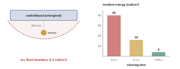
The hazard is measured by the incident energy: the thermal energy per unit area at a specified working distance (typically 455 mm, about 18 in, for LV equipment), expressed in calories per square centimeter (cal/cm²). An exposure of about 1.2 cal/cm² is the threshold for the onset of a second-degree burn on bare skin. The arc flash boundary is the distance from the equipment at which incident energy falls to 1.2 cal/cm²; inside it, arc-rated protective clothing is required.
Incident energy is calculated with the empirical model of IEEE 1584 (2018 edition), which depends on the system voltage, the arcing current (lower than the bolted fault current), the gap between conductors, the enclosure size and electrode configuration, the working distance and, most importantly, the arcing time: how long the arc lasts before an upstream device clears it. Incident energy is roughly proportional to arcing time, which gives designers their most powerful lever.
Worked problem
The effect of clearing time
An arc flash study finds 40 cal/cm² at a switchboard because the upstream breaker has a 0.5 s short-time delay for coordination. If an arc energy reduction method makes the breaker clear in 0.05 s during maintenance, and the arcing current is unchanged, estimate the new incident energy.
Show solution
- Incident energy is approximately proportional to arcing time.
- New energy \(\approx 40 \times 0.05/0.5 = 4\) cal/cm².
Answer: About 4 cal/cm², a tenfold reduction, moving the required protective clothing from the heaviest category to the lightest. This is why maintenance modes that temporarily speed up tripping are so valuable. (A real study recalculates with IEEE 1584, but the proportionality is a good first estimate.)
PPE categories and labels
Workers who must be within the arc flash boundary wear arc-rated clothing and equipment. Standards define four PPE categories by the minimum arc rating of the clothing:
| PPE category | Minimum arc rating | Typical clothing |
|---|---|---|
| 1 | 4 cal/cm² | Arc-rated shirt and trousers or coverall, face shield, hard hat |
| 2 | 8 cal/cm² | Arc-rated shirt and trousers or coverall, arc-rated balaclava and face shield or hood |
| 3 | 25 cal/cm² | Arc flash suit with hood, arc-rated gloves |
| 4 | 40 cal/cm² | Heavier arc flash suit with hood, arc-rated gloves |
Above 40 cal/cm², the blast and pressure effects make energized work unacceptable regardless of clothing, and the equipment must be de-energized. Every piece of equipment that might be worked on while energized carries an arc flash label stating at least the nominal voltage, the arc flash boundary and either the incident energy at the working distance or the required PPE category, together with the date of the study. Labels must be updated when the system changes.
In the US, the workplace electrical safety standard is NFPA 70E, Standard for Electrical Safety in the Workplace, used by employers to meet the general requirements of OSHA. The NEC (Section 110.16) requires arc flash warning labels on equipment likely to be worked on while energized, with more detailed information required on service equipment and other large equipment, including the date of the assessment.
Reducing the hazard
The safest approach, required by the standards, is to de-energize equipment and establish an electrically safe work condition (lockout, tagout, testing for absence of voltage) before working on it. Energized work is allowed only when de-energizing would create a greater hazard or is infeasible, and it requires a documented justification, an energized work permit and appropriate PPE. In a 2N data center, the redundant path usually makes de-energizing one side feasible, which is one of the strongest operational arguments for that architecture.
Where equipment must be worked on live, designers reduce incident energy with:
- Energy-reducing maintenance switching: a switch that temporarily sets a breaker to trip instantaneously, with an indicator, while work is in progress.
- Zone-selective interlocking and bus differential protection, which clear faults within the protected zone without coordination delays.
- Current-limiting fuses, which clear high currents in less than half a cycle.
- Arc-resistant switchgear, remote racking of breakers and remote operation, which put distance between the worker and the arc.
- Lower fault current, through transformer impedance and system design (Lesson 3).
The NEC requires an arc energy reduction method on breakers rated or adjustable to 1200 A or more (Section 240.87) and on fused equipment of the same size (Section 240.67), and NFPA 70E places elimination and engineering controls ahead of PPE.
Maintenance
Protective devices only work as calculated if they are maintained. A breaker that has not operated in years can trip slowly, which lengthens arcing time and raises incident energy far above the label value. Periodic testing of breakers and relays, infrared scanning of connections, and cleaning and torque checks are part of every data center maintenance program, and the condition of the equipment is an input to the arc flash study.
Common mistakes
MistakeChecking interrupting ratings against the transformer's full-load current.
InsteadRatings must exceed the available short-circuit current at each location, which is far higher.
MistakeAssuming generator or UPS operation gives the same protection performance as utility power.
InsteadGenerators and inverters supply much less fault current; check that faults still clear quickly on every source.
MistakeLengthening breaker delays for coordination without checking arc flash.
InsteadLonger delays increase arcing time and incident energy; use ZSI, differential protection or maintenance switching.
MistakeTreating PPE as the first line of defense.
InsteadDe-energize where possible; reduce energy by design; PPE is the last line of defense.
MistakeLeaving arc flash labels unchanged after system changes.
InsteadUpdate the short-circuit, coordination and arc flash studies and labels whenever sources, settings or equipment change.
Summary and key terms
- Bolted three-phase fault current \(I_{\text{SC}} = V_{LL}/(\sqrt{3}Z_{\text{total}})\), summing source, transformer and conductor impedances.
- Fault current is highest at the transformer and falls along feeders; motors add to it, generators and UPS inverters supply much less.
- Every device and assembly must be rated for the available fault current at its location.
- Selective coordination makes the device nearest a fault trip first; it is checked on time-current curves and aided by short-time delays, ZSI and tested selectivity tables.
- Arc flash incident energy (cal/cm²) is calculated with IEEE 1584 and is roughly proportional to arcing time; the boundary is where it falls to 1.2 cal/cm².
- PPE categories 1–4 require 4, 8, 25 and 40 cal/cm²; above 40, energized work is not acceptable.
- De-energize first; reduce energy with maintenance switching, ZSI, differential protection, current-limiting fuses and remote operation.
- Maintained protective devices and up-to-date labels keep the studies valid.
- Short circuit
- An unintended low-impedance connection between conductors or to ground.
- Bolted fault
- A short circuit with negligible fault impedance, giving the maximum fault current.
- Available fault current
- The maximum short-circuit current that can flow at a given point.
- Short-circuit current rating (SCCR)
- The fault current an assembly can withstand safely.
- Series rating
- A tested combination allowing a lower-rated device behind a current-limiting upstream device.
- Selective coordination
- Protection arranged so only the device nearest a fault operates.
- Time-current curve
- A log-log plot of a protective device's operating time against current.
- Zone-selective interlocking
- Communication between breakers so the one nearest a fault trips without delay and others wait.
- Arc flash
- The release of heat, light and pressure from an electric arc through air.
- Incident energy
- Thermal energy per unit area at a working distance from an arc, in cal/cm².
- Arc flash boundary
- The distance at which incident energy falls to 1.2 cal/cm².
- Arcing time
- The duration of an arc, set by how quickly the upstream protection clears it.
- PPE category
- A level of arc-rated protective equipment defined by minimum arc rating.
- Electrically safe work condition
- A state in which equipment has been isolated, locked out and tested for absence of voltage.
- Energized work permit
- A documented authorization and plan for justified work on live equipment.
- IEEE 1584
- The IEEE guide for performing arc flash hazard calculations.
Practice problems
Work each problem on paper first, then reveal the answer to check.
A 1500 kVA, 480 V transformer has 5.75% impedance. Find its impedance in ohms and the infinite-source fault current.
Show answer
Z = 0.48²/1.5 × 0.0575 = 0.00883 Ω; I_SC = 480/(1.732 × 0.00883) = 31.4 kA.
Add a feeder of 0.003 Ω to the previous transformer. Estimate the fault current at its end.
Show answer
Z = 0.01183 Ω; I_SC = 480/(1.732 × 0.01183) = 23.4 kA.
A utility has a fault level of 250 MVA at the service. Convert it to an impedance at 600 V.
Show answer
Z = 0.6²/250 = 0.00144 Ω.
A panelboard has 22 kA rated breakers, and the available fault current at its location is 26 kA. What are two acceptable solutions?
Show answer
Replace with breakers (and panelboard) rated at least 26 kA; or use a tested series-rated combination with a current-limiting upstream device; or add impedance (longer or smaller feeder, or a transformer) to reduce fault current below 22 kA.
Why does a generator contribute much less fault current than the utility?
Show answer
Its subtransient reactance (10–20%) limits fault current to roughly 5–10 times rated current, and that decays quickly; the utility source is far stronger.
A main breaker's short-time delay is raised from 0.2 s to 0.4 s to improve coordination. What happens to the incident energy at its load-side bus?
Show answer
It roughly doubles, because incident energy is approximately proportional to arcing time.
A label shows 11 cal/cm². What is the minimum PPE category, and what minimum arc rating must the clothing have?
Show answer
Category 3 (25 cal/cm² minimum); category 2's 8 cal/cm² is insufficient. If incident energy is used directly, clothing rated at least 11 cal/cm² is required.
Explain how zone-selective interlocking improves both coordination and arc flash.
Show answer
Downstream breakers that see a fault send a restraint signal so upstream breakers wait (coordination); when a fault is in the upstream breaker's own zone, no restraint arrives and it trips without its intentional delay, cutting arcing time.
What is the first step required before working on electrical equipment, according to CSA Z462 and NFPA 70E?
Show answer
Establish an electrically safe work condition (de-energize, lock out, test for absence of voltage) unless that is infeasible or creates a greater hazard.
Why must short-circuit and arc flash studies be updated after replacing a utility transformer with a larger one?
Show answer
A larger or lower-impedance transformer raises available fault current, which can exceed equipment ratings and change arcing current and clearing times, so the labels and ratings may no longer be valid.
Lesson quiz · 5 questions
Score 60% or more to complete this lesson.
Create a free account to save your progress, take quizzes and earn a certificate.