
DCE-310 · Lesson 6 of 12 · 31 min
Low-voltage conductors, raceways and circuit sizing
Lesson 5 laid out the low-voltage chain from switchboards to rack PDUs. Connecting those pieces takes thousands of meters of cable, conduit, cable tray and busway, and each run must be sized correctly: large enough to carry its load without overheating, to keep voltage drop within limits and to clear faults safely, but no larger than necessary, because copper is expensive and space in electrical rooms and pathways is scarce. This lesson works through low-voltage circuit sizing as practiced in data centers: continuous loads and overcurrent devices, ampacity and its corrections, voltage drop, parallel conductors, neutrals and harmonics, copper versus aluminum, and the raceways that carry it all.
The sizing sequence
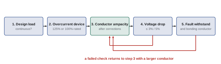
A low-voltage feeder or branch circuit is sized in a fixed order, and each step can only increase the conductor size found in the previous one:
1. Determine the design load current (Lesson 2), and whether it is continuous (expected to run for three hours or more, which almost every data center load is).
2. Choose the overcurrent device rating: for continuous loads, at least 125% of the load current, unless the device and its enclosure are listed for 100% continuous operation (Lesson 11).
3. Choose conductors whose ampacity, after all correction factors, is at least the larger of the overcurrent device rating (with permitted round-up rules) and 125% of the continuous load.
4. Check voltage drop and increase the size if needed.
5. Check that the conductors can withstand the available fault current until the protective device clears it, and size the equipment grounding (bonding) conductor.
Ampacity and termination temperature
Conductor ampacity tables give the current a conductor can carry continuously at a stated ambient temperature (30 °C) without exceeding the temperature rating of its insulation, for a small number of current-carrying conductors together. Insulation is commonly rated 75 °C or 90 °C. However, the terminals of breakers and equipment are usually rated only 75 °C (and 60 °C for small sizes), so the ampacity used for the final selection is normally taken from the 75 °C column even if the cable is rated 90 °C. The 90 °C column may be used as the starting point for applying correction factors.
| Copper size | 75 °C ampacity (A) | 90 °C ampacity (A) |
|---|---|---|
| 1/0 AWG | 150 | 170 |
| 3/0 AWG | 200 | 225 |
| 4/0 AWG | 230 | 260 |
| 250 kcmil | 255 | 290 |
| 350 kcmil | 310 | 350 |
| 500 kcmil | 380 | 430 |
Correction and adjustment factors
Two corrections are applied to the table values:
- Ambient temperature: above 30 °C, ampacity is reduced. For 90 °C insulation at 40 °C ambient, the factor is 0.91; for 75 °C insulation at 40 °C, 0.88. Electrical rooms in data centers can run warm, and cables routed above hot aisles or near heat sources may see ambients well above 30 °C.
- Number of current-carrying conductors: with more than three in one raceway or cable, mutual heating reduces ampacity: 80% for 4 to 6 conductors, 70% for 7 to 9, and lower for more.
Worked problem
Applying corrections
Two three-phase circuits (six current-carrying conductors) of 4/0 AWG copper with 90 °C insulation share a conduit in a 40 °C space. The terminals are rated 75 °C. What is the usable ampacity?
Show solution
- Start from the 90 °C ampacity: 260 A.
- Corrections: \(260 \times 0.91 \times 0.80 = 189\) A.
- Termination limit: the 75 °C ampacity of 4/0 is 230 A.
- Usable ampacity: the smaller, 189 A.
Answer: 189 A per conductor. Running the two circuits in separate conduits would remove the 0.80 factor and give \(260 \times 0.91 = 237\) A, limited to 230 A by the terminals: separating circuits is often cheaper than upsizing them.
Sizing a feeder for a continuous load
Worked problem
A PDU feeder
A PDU draws 400 A continuously at 415 V (or 480 V) three-phase. The feeder breaker is a standard (80%-rated) breaker. Copper conductors with 75 °C terminations run in their own conduits at 30 °C ambient. Size the breaker and conductors.
Show solution
- Breaker: \(1.25 \times 400 = 500\) A; choose a 500 A breaker.
- Conductors: ampacity at least 500 A. No single conductor in the table reaches 500 A at 75 °C, so use two conductors per phase in parallel.
- Two sets of 250 kcmil: \(2 \times 255 = 510\) A ≥ 500 A. Two sets of 4/0 (\(2 \times 230 = 460\) A) are too small.
- Each parallel set runs in its own conduit with all three phases (and the neutral and bonding conductor if required), so no adjustment factor applies.
Answer: A 500 A breaker with two parallel sets of 250 kcmil copper per phase. With a 100%-rated breaker the breaker and conductors could be sized at 400 A instead, saving copper, which is one reason 100%-rated equipment is common in data centers.
Large feeders are almost always run as parallel sets. Codes permit paralleling only for conductors of 1/0 AWG and larger, and require every parallel conductor of a phase to be the same length, material, size and insulation, terminated the same way, so that the current divides equally. Each raceway must contain one conductor of every phase, so that the magnetic fields cancel and steel conduits are not heated by induced currents.
Voltage drop
Codes and good practice limit voltage drop so that equipment receives adequate voltage: a common target is 3% on a feeder or branch circuit and 5% in total from the service to the load. For a three-phase circuit,
where \(R\) and \(X\) are the conductor resistance and reactance per unit length at operating temperature.
Worked problem
Voltage drop to a remote PDU
A 415 V three-phase feeder 200 ft (61 m) long carries 100 A at power factor 0.95 to a PDU. The conductors have \(R = 0.24\) Ω/km and \(X = 0.08\) Ω/km at operating temperature. Find the voltage drop.
Show solution
- \(\sin\phi = 0.312\).
- \(\Delta V = 1.732 \times 100 \times 0.060 \times (0.24 \times 0.95 + 0.08 \times 0.312) = 10.39 \times 0.253 = 2.63\) V.
- As a percentage: \(2.63/415 = 0.63\%\).
Answer: About 2.6 V, or 0.63%, well within limits. Voltage drop rarely governs inside a data hall at 415 V or 480 V; it matters for long runs at 208 V and below, for DC distribution (ELE-202, Lesson 11), and in rack-level busbars.
Neutrals and harmonics
In a balanced three-phase four-wire system with linear loads, the neutral carries almost no current, because the three phase currents cancel. The switch-mode power supplies of IT equipment, however, draw current in short pulses rich in harmonics, especially the third harmonic and its multiples (the triplen harmonics). Triplen harmonics from the three phases are in phase with each other, so instead of canceling in the neutral they add.
Worked problem
Neutral current from triplen harmonics
Each phase of a 208Y/120 V panel carries 100 A RMS of which the third-harmonic component is 33 A RMS. Ignoring other harmonics and assuming balanced loads, estimate the neutral current.
Show solution
- Fundamental components cancel in the neutral.
- Third-harmonic components add: \(3 \times 33 = 99\) A.
Answer: About 99 A in the neutral, as much as each phase. Panels serving single-phase IT loads therefore use full-size neutrals or oversized (200%) neutrals, and transformers feeding them may be K-rated (Lesson 8). The problem has diminished as modern server power supplies use active power factor correction, and is avoided entirely where IT equipment is fed line to line at 208 V or from 415Y/240 V systems with balanced phase loading.
A neutral that carries significant harmonic current counts as a current-carrying conductor when applying the adjustment factors above.
Copper or aluminum?
Aluminum conductors are lighter and much cheaper than copper for the same ampacity, but have about 61% of copper's conductivity, so they must be about two sizes larger. Aluminum has a reputation for failures at terminations, mostly from older alloys and poor installation; modern AA-8000 series alloys with properly rated, correctly torqued terminations perform well. Aluminum is widely used for large feeders and busway; copper remains standard for branch circuits and wherever space is tight.
Worked problem
Comparing materials
A feeder needs 380 A of 75 °C ampacity. 500 kcmil copper provides 380 A; 750 kcmil aluminum provides 385 A. If copper cable costs $60 per meter per conductor and aluminum $22, compare the conductor cost for four conductors (three phases and neutral) over 80 m.
Show solution
- Copper: \(4 \times 80 \times 60 = \$19{,}200\).
- Aluminum: \(4 \times 80 \times 22 = \$7{,}040\).
Answer: Aluminum saves about $12,000 on this run (prices are illustrative and volatile), at the cost of larger conduits, larger lugs and more space. The decision weighs material cost against space, termination quality and the owner's standards.
Raceways, cable tray and fill
Conductors run in raceways: rigid or electrical metallic conduit (EMT), cable tray, wireways and busway. Each has rules:
- Conduit fill: conductors may fill only a set percentage of a conduit's cross-section (40% for three or more conductors), so that they can be pulled without damage and can shed heat.
- Cable tray: suitable cable types only, with fill limits based on cable diameters and tray width, and separation between power and data cabling. In data halls, overhead cable trays for power and network cabling must be coordinated with busway, lighting, sprinklers, containment and cooling (DCE-320).
- Bending radius and pulling tension limits protect large cables during installation.
- Fire-stopping must restore the fire rating wherever raceways pass through fire-rated walls and floors (DCE-440).
In the US, conductor sizing follows Article 310 of the National Electrical Code (ampacity tables and correction factors), Articles 210 and 215 for branch circuits and feeders, Article 392 for cable trays and the raceway articles of Chapter 3.
Common mistakes
MistakeUsing the 90 °C ampacity for the final size with 75 °C terminals.
InsteadFinal ampacity must not exceed the termination temperature rating.
MistakeForgetting ambient and bundling corrections.
InsteadApply both, starting from the insulation rating column.
MistakeRunning parallel sets with unequal lengths or one phase per conduit.
InsteadMake parallel conductors identical and put all phases in each raceway.
MistakeSizing neutrals for balanced linear load only.
InsteadAllow for triplen harmonic current from single-phase IT loads.
MistakeIgnoring voltage drop on long 208 V or DC runs.
InsteadCalculate it and upsize where needed.
Summary and key terms
- Size circuits in order: load, overcurrent device, ampacity, voltage drop, fault withstand.
- Continuous loads need 125% overcurrent devices and conductors unless 100%-rated equipment is used.
- Use the 75 °C column for final ampacity with 75 °C terminals; apply ambient and bundling corrections.
- Large feeders use identical parallel sets with all phases in each raceway.
- Voltage drop targets are about 3% per circuit and 5% total.
- Triplen harmonics add in the neutral; size neutrals accordingly.
- Aluminum saves cost and weight at the expense of size; raceway fill and fire-stopping rules apply.
- Ampacity
- The current a conductor can carry continuously without exceeding its temperature rating.
- Continuous load
- A load expected to run for three hours or more.
- Termination rating
- The temperature rating of the terminals a conductor connects to.
- Correction factor
- A multiplier reducing ampacity for ambient temperature.
- Adjustment factor
- A multiplier reducing ampacity for more than three current-carrying conductors.
- Parallel conductors
- Two or more identical conductors per phase sharing current.
- Voltage drop
- The reduction in voltage along a conductor due to its impedance.
- Triplen harmonics
- Harmonics at multiples of three times the fundamental, which add in the neutral.
- Conduit fill
- The fraction of a conduit's area occupied by conductors.
- Fire-stopping
- Sealing penetrations to restore fire-resistance ratings.
Practice problems
Work each problem on paper first, then reveal the answer to check.
A continuous load of 160 A. Minimum standard breaker rating?
Show answer
200 A (125% = 200 A).
Same load with a 100%-rated breaker?
Show answer
160 A minimum (175 A is the next standard size if 160 A is unavailable).
350 kcmil copper, 90 °C insulation, 40 °C ambient, alone in conduit, 75 °C terminals. Usable ampacity?
Show answer
min(350 × 0.91 = 318.5, 310) = 310 A.
Same with six current-carrying conductors in the conduit?
Show answer
350 × 0.91 × 0.80 = 255 A.
Two parallel sets of 3/0 copper at 75 °C. Ampacity?
Show answer
400 A.
Smallest conductor size that may be paralleled?
Show answer
1/0 AWG.
50 A three-phase over 100 m, R = 0.5 Ω/km, X ≈ 0, pf 1. Voltage drop?
Show answer
1.732 × 50 × 0.1 × 0.5 = 4.33 V.
As a percentage of 208 V?
Show answer
2.1%.
Phase third harmonic 20 A RMS, balanced. Neutral current?
Show answer
About 60 A.
Maximum conduit fill for three or more conductors?
Show answer
40%.
Lesson quiz · 5 questions
Score 60% or more to complete this lesson.
Create a free account to save your progress, take quizzes and earn a certificate.