
DCE-310 · Lesson 4 of 12 · 27 min
Medium-voltage cables, duct banks and system grounding
Lesson 3 described the medium-voltage (MV) switchgear and transformers that distribute power around a campus. Between them run the cables, usually underground in concrete-encased duct banks, and beneath every part of the system lies a decision about how it is connected to earth. Both are easy to overlook on a one-line diagram and both cause long, expensive outages when they go wrong: an MV cable fault can take days to locate and repair, and the system grounding method decides whether a single ground fault trips a whole building or merely sounds an alarm. This lesson covers MV cable construction and ratings, how heat limits what a duct bank can carry, testing and failure, and the grounding of MV and low-voltage systems.
Medium-voltage cable construction
An MV power cable is a carefully layered structure designed to keep a strong electric field evenly contained:
- Conductor: stranded copper or aluminum.
- Conductor shield: a thin semiconducting layer that smooths the surface of the strands so the electric field is uniform.
- Insulation: usually cross-linked polyethylene (XLPE) or ethylene propylene rubber (EPR), several millimeters thick, rated for a continuous conductor temperature of 90 °C (105 °C for some EPR), 130 °C in emergency overload and 250 °C during short circuits.
- Insulation shield: another semiconducting layer that confines the field inside the insulation.
- Metallic shield: copper tape or wires, grounded, which carries charging current and fault current and keeps the outside of the cable at ground potential.
- Jacket: an outer protective layer of PVC or polyethylene.
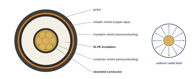
Because the insulation is highly stressed, any defect, such as a void, a sharp protrusion, water ingress or a poorly prepared joint, concentrates the field and starts partial discharge, tiny sparks that slowly erode the insulation until it fails. Most MV cable failures occur at terminations and splices, where the factory-made layers are cut and rebuilt by hand in the field, which is why only trained, certified cable splicers should do this work and why manufacturers' kits and instructions must be followed exactly.
Insulation levels
MV cable is specified by its voltage class and insulation level. A 100% insulation level suits systems where ground faults are cleared within about one minute, which is the case for solidly and low-resistance grounded systems. A 133% level, with thicker insulation, is used where faults may persist for up to an hour, as on ungrounded or high-resistance grounded systems, because during a ground fault on such systems the unfaulted phases rise to full line-to-line voltage above ground.
Ampacity: heat is the limit
A cable's ampacity is the current it can carry continuously without its conductor exceeding its rated temperature. Heat generated by \(I^{2}R\) losses must flow out through the insulation, the duct, the concrete and the surrounding soil to the ground surface. Every layer adds thermal resistance, so ampacity depends far more on the installation than on the cable itself:
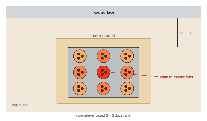
- Soil thermal resistivity: moist soil conducts heat well (around 0.9 K·m/W); dry sand can be over 2.5 K·m/W, cutting ampacity substantially. Engineers measure soil thermal resistivity on site, and specify a thermal backfill with known properties around duct banks.
- Burial depth and spacing: deeper or closer cables run hotter.
- Mutual heating: in a duct bank of many circuits, each cable is heated by its neighbors, and the cables in the middle of the bank run hottest.
- Load factor: cyclic loads let the soil cool between peaks; data center loads are nearly constant, so little benefit is available.
Ampacities for standard installations are tabulated in the electrical codes; for real duct banks, engineers calculate them with the Neher–McGrath method (IEEE 835 tables) or IEC 60287, usually in software.
Worked problem
Derating for a duct bank
A 25 kV feeder must carry 600 A continuously. One circuit of the chosen cable is rated 500 A in a single isolated duct. In the planned nine-duct bank, calculations show that mutual heating reduces each circuit's ampacity to 70% of its single-duct value. How many parallel circuits are needed?
Show solution
- Ampacity per circuit in the bank: \(0.70 \times 500 = 350\) A.
- Circuits needed: \(600/350 = 1.71\), so two circuits.
- Check: two circuits carry 300 A each, below 350 A. (Adding a second circuit to the bank also adds heat, so the calculation must be rerun with the final arrangement.)
Answer: Two parallel circuits of the cable. A larger conductor might also work, but parallel circuits give redundancy and keep cables to a size that can be pulled and terminated. Mutual heating is often the controlling factor in a large campus duct bank.
Voltage drop and losses on MV feeders
Because MV currents are modest, voltage drop is rarely a problem over the distances within a campus, but it should be checked, together with the losses, for long feeders. For a three-phase feeder of length \(L\) with resistance \(r\) and reactance \(x\) per unit length, carrying current \(I\) at power factor angle \(\phi\):
Worked problem
A campus feeder
A 25 kV feeder 3 km long carries 20 MVA at power factor 0.95. Its cable has \(r = 0.10\) Ω/km and \(x = 0.12\) Ω/km per phase. Find the current, the voltage drop and the losses.
Show solution
- Current: \(I = 20{,}000/(\sqrt{3} \times 25) = 462\) A.
- \(\sin\phi = \sqrt{1 - 0.95^{2}} = 0.312\).
- Drop: \(1.732 \times 462 \times 3 \times (0.10 \times 0.95 + 0.12 \times 0.312) = 1.732 \times 462 \times 3 \times 0.1325 = 318\) V, or 1.3%.
- Losses: \(3I^{2}rL = 3 \times 462^{2} \times 0.10 \times 3 = 192\) kW, about 1% of the load.
Answer: About 462 A, a 1.3% voltage drop and 192 kW of losses. The losses cost money every hour of every year: at $0.08 per kWh, 192 kW is about $135,000 a year, which can justify larger conductors on long, heavily loaded feeders.
Testing and failure
New MV cables are tested after installation and before energization, and many operators test them periodically. Common tests (IEEE 400 series) include:
- Insulation resistance with a high-voltage DC tester: a quick check for gross defects.
- Very low frequency (VLF) withstand: applying an AC voltage at about 0.1 Hz at several times normal voltage for a set time; good insulation withstands it, while weak spots fail during the test rather than in service.
- Tan delta (dissipation factor): measuring how lossy the insulation is, which rises as it ages or absorbs water.
- Partial discharge testing: detecting and locating the tiny discharges that signal defects, especially in terminations and splices.
When an underground cable fails, the fault must be located before it can be repaired, using techniques such as time-domain reflectometry and "thumping" (applying high-voltage pulses and listening for the discharge at the fault). Repairs can take days. That is why critical facilities use ring or dual-radial MV arrangements (Lesson 3) so that any single cable can be lost without losing load, and keep spare cable, splice kits and contracted repair crews on hand.
System grounding
System grounding means the intentional connection of a power system's neutral (or one conductor) to earth. It is different from equipment grounding and bonding, which connect the metal enclosures of equipment together and to earth for safety (Lesson 9). The choice of system grounding determines what happens during the most common fault: a single phase touching ground.
| Method | Ground fault current | On a ground fault | Typical use |
|---|---|---|---|
| Solidly grounded | High, comparable to phase faults | Trips immediately | Low-voltage systems (208Y/120 V, 480Y/277 V, 600Y/347 V); many utility systems |
| Low-resistance grounded | Limited, typically 200 A to 1,000 A | Trips quickly, with less damage | Medium-voltage industrial and campus systems |
| High-resistance grounded | Limited to a few amperes (typically 1 A to 10 A) | Alarms; can keep running while the fault is found | Low-voltage systems where continuity matters, such as 480 V or 600 V mechanical loads |
| Ungrounded | Very small (capacitive charging current) | Alarms; risk of transient overvoltages | Older industrial systems; now uncommon |
Resistance grounding inserts a neutral grounding resistor (NGR) between the transformer neutral and earth, limiting the fault current to a value set by Ohm's law. A high-resistance grounding resistor must allow more current than the system's capacitive charging current, or transient overvoltages can build up during arcing faults.
Worked problem
Sizing grounding resistors
(a) A 13.8 kV system is to be low-resistance grounded with ground fault current limited to 400 A. Find the resistor value. (b) A 480 V system is to be high-resistance grounded with ground fault current limited to 5 A; its measured charging current is 2.2 A. Find the resistor value and check it.
Show solution
- (a) Line-to-neutral voltage: \(13{,}800/\sqrt{3} = 7{,}967\) V. \(R = 7{,}967/400 = 19.9\) Ω.
- (b) Line-to-neutral voltage: \(480/\sqrt{3} = 277\) V. \(R = 277/5 = 55.4\) Ω.
- Check: the resistor current (5 A) exceeds the charging current (2.2 A), as required.
Answer: About 19.9 Ω at 13.8 kV and 55.4 Ω at 480 V. At 400 A, a 13.8 kV ground fault still does little damage before relays trip it within a fraction of a second; at 5 A, the 480 V system can keep running while staff find the fault, which is valuable for critical cooling loads. High-resistance grounding cannot be used where loads are connected line to neutral, because there is no solidly grounded neutral to serve them.
Data centers typically use solidly grounded systems for the IT distribution (so that single-phase loads can be served and ground faults trip promptly), low-resistance grounding on the MV system, and sometimes high-resistance grounding on 480 V or 600 V mechanical systems, where riding through a first ground fault keeps chillers and pumps running.
In the US, the National Electrical Code permits high-impedance grounded neutral systems at 480 V to 1,000 V only under conditions such as qualified maintenance and ground detection (250.36), and covers systems over 1,000 V in the articles for higher voltages.
Common mistakes
MistakeTaking cable ampacity from a table without considering the installation.
InsteadCalculate ampacity for the real duct bank, soil resistivity, depth and mutual heating.
MistakeAllowing untrained workers to make MV terminations and splices.
InsteadUse certified splicers and the manufacturer's kits and procedures.
MistakeUsing 100% insulation on a high-resistance grounded MV system.
InsteadUse 133% insulation where ground faults may persist.
MistakeSizing a high-resistance grounding resistor below the charging current.
InsteadThe resistor current must exceed the capacitive charging current.
MistakeRelying on a single MV cable path to a critical building.
InsteadProvide ring or dual-radial feeds with diverse routes.
Summary and key terms
- MV cables layer conductor, semiconducting shields, insulation, metallic shield and jacket to control the electric field.
- Terminations and splices are the weak points; partial discharge erodes defects to failure.
- Ampacity is limited by heat flow through soil and concrete; mutual heating in duct banks dominates.
- Voltage drop is small on campus MV feeders, but losses can justify larger conductors.
- VLF, tan delta and partial discharge tests assess cable condition.
- System grounding (solid, low-resistance, high-resistance) sets ground fault current and behavior.
- Resistor values follow from Ohm's law using line-to-neutral voltage.
- XLPE
- Cross-linked polyethylene, the most common MV cable insulation.
- Semiconducting shield
- A layer that smooths and confines the electric field in a cable.
- Partial discharge
- Small localized discharges in insulation defects.
- Insulation level
- The insulation thickness class, 100% or 133%, based on fault-clearing time.
- Thermal resistivity
- A material's resistance to heat flow, in K·m/W.
- Duct bank
- An array of conduits encased in concrete, usually buried.
- Mutual heating
- Heating of a cable by nearby cables.
- VLF test
- A withstand test at very low frequency, about 0.1 Hz.
- System grounding
- The intentional connection of a power system's neutral to earth.
- Neutral grounding resistor
- A resistor between the neutral and earth that limits ground fault current.
Practice problems
Work each problem on paper first, then reveal the answer to check.
Name the layers of an MV cable from the inside out.
Show answer
Conductor, conductor shield, insulation, insulation shield, metallic shield, jacket.
Where do most MV cable failures occur?
Show answer
At terminations and splices.
When is 133% insulation used?
Show answer
Where ground faults may persist, as on ungrounded or high-resistance grounded systems.
Why does dry soil reduce ampacity?
Show answer
Its higher thermal resistivity traps heat.
A circuit rated 400 A alone is derated to 75% in a bank. Circuits for 800 A?
Show answer
3 (300 A each available).
15 MVA at 13.8 kV. Current?
Show answer
628 A.
Losses of 3 × 300² × 0.2 Ω. Value?
Show answer
54 kW.
Low-resistance grounding at 25 kV limited to 600 A. Resistor?
Show answer
24.1 Ω.
High-resistance grounding at 600 V limited to 5 A. Resistor?
Show answer
69.3 Ω.
Why not use high-resistance grounding on 208Y/120 V IT distribution?
Show answer
Single-phase line-to-neutral loads need a solidly grounded neutral.
Lesson quiz · 5 questions
Score 60% or more to complete this lesson.
Create a free account to save your progress, take quizzes and earn a certificate.