
DCE-310 · Lesson 10 of 12 · 30 min
Metering, monitoring and control
An electrical system that cannot be seen cannot be operated safely or efficiently. A large data center has thousands of meters, relays, breakers and sensors, and the people running it need to know, at every moment, how much load each part of the system carries, how much redundancy remains, whether power quality is normal, and what happened in the milliseconds before any trip. This lesson describes the electrical power monitoring system (EPMS) that gathers that information: the meters and their accuracy, the metering hierarchy behind PUE, branch circuit monitoring and capacity management, the communication protocols, time synchronization, automated control such as load shedding, and the cybersecurity that must protect it all.
The electrical power monitoring system
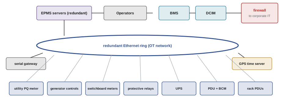
An EPMS (sometimes called a power management system or electrical SCADA) collects data from every intelligent device in the electrical system and presents it to operators. A typical architecture has three levels:
- Field devices: revenue-grade and power quality meters at the utility service and generator buses; meters in switchboards, UPS systems and PDUs; microprocessor protective relays (Lesson 3); breaker trip units; branch circuit monitors; and status contacts from transfer switches and breakers.
- Network: dedicated Ethernet networks (usually redundant rings) and gateways that convert older serial protocols, physically separate from the business IT network.
- Servers and software: redundant servers that poll and store the data, display one-line diagrams with live values, raise alarms, analyze power quality events, and produce reports for energy, capacity and billing.
The EPMS is often integrated with, or feeds, the building management system (BMS), which controls mechanical systems, and the data center infrastructure management (DCIM) system, which tracks IT assets, space and capacity.
Meters and accuracy
Electronic power meters sample voltage and current waveforms thousands of times per cycle and compute RMS values, real, reactive and apparent power, energy, power factor, harmonics and demand. Their accuracy is specified by class:
- Revenue-grade meters (for example accuracy class 0.2 or 0.5 under IEC 62053 or ANSI C12.20) at the utility service and wherever energy is billed to tenants: ±0.2% to ±0.5% of reading.
- Power quality meters, which add waveform capture and event recording (Lesson 8).
- General-purpose panel meters and the metering built into UPS systems and PDUs, typically ±1% or so.
A meter is only as accurate as its current transformers (CTs) and voltage connections. CTs have their own accuracy classes, and errors from wrongly sized CTs (operating at a few percent of their rating), reversed polarity or mismatched phases are among the most common metering problems found during commissioning.
Metering for PUE
PUE (DCE-200) is total facility energy divided by IT energy. Its value depends on where the IT energy is measured, so the standard ISO/IEC 30134-2 defines categories:
- Category 1: IT energy measured at the UPS outputs.
- Category 2: measured at the PDU outputs, after PDU transformer and distribution losses.
- Category 3: measured at the IT equipment input, for example at the rack PDUs.
Measuring closer to the IT equipment gives a smaller IT energy figure (losses in between count as facility overhead) and therefore a higher, more honest PUE. Reported PUE values should always state their category and measurement period.
Worked problem
PUE and its uncertainty
Over a year, the utility revenue meter (±0.2%) records 115,600 MWh, and the UPS output meters (±1% each) record 87,600 MWh of IT energy. (a) What is the category 1 PUE? (b) Roughly how uncertain is it?
Show solution
- (a) \(PUE = 115{,}600/87{,}600 = 1.320\).
- (b) For a ratio, relative uncertainties combine approximately in quadrature: \(\sqrt{0.2^{2} + 1^{2}} = 1.02\%\).
- Uncertainty: \(1.320 \times 0.0102 = 0.013\).
Answer: A PUE of 1.32 ± 0.013. An efficiency project claiming to have improved PUE from 1.32 to 1.31 cannot be confirmed with these meters; better IT-side metering, or comparisons made with the same meters before and after, are needed.
Branch circuit monitoring and capacity management
Branch circuit monitoring (BCM) measures the current in every circuit leaving a PDU or remote power panel, and intelligent rack PDUs measure each outlet or inlet. With thousands of circuits, this data supports three tasks:
- Protecting circuits: alarms before any circuit approaches its continuous rating (80% of the breaker rating for standard breakers, Lesson 11).
- Protecting redundancy: for dual-corded racks, the sum of the A and B circuit loads must stay within what one circuit can carry, because that is what will happen if either path fails (Lesson 5). A rack whose A and B circuits each carry 60% of rating looks healthy but will trip on failover.
- Capacity management: comparing contracted, allocated and measured power at every level, from rack to UPS block to utility service, to find stranded capacity and to stop oversubscription before it becomes risky (Lesson 2).
Worked problem
A hidden failover risk
A rack is fed by A and B circuits, each 208 V three-phase 30 A with a standard breaker (continuous limit 24 A). Monitoring shows 15 A on A and 14 A on B. Is the rack safe? What alarm rule would catch this?
Show solution
- Each circuit alone is at \(15/24 = 63\%\) and \(14/24 = 58\%\) of its continuous limit: no individual alarm.
- On failover, one circuit carries \(15 + 14 = 29\) A, above the 24 A continuous limit and close to the 30 A breaker rating. With power supplies sharing unevenly, the breaker may trip.
- Rule: alarm when \(I_{A} + I_{B}\) exceeds 80% of one circuit's rating (24 A).
Answer: The rack is not safe for failover: its combined load of 29 A exceeds what one circuit can carry continuously. The A + B rule, applied across every dual-corded rack, is one of the most valuable outputs of branch circuit monitoring, because a single upstream failure would otherwise trip many such racks at once.
Communication protocols
Field devices speak a variety of protocols:
- Modbus, in serial (RTU over RS-485) and Ethernet (TCP) forms: simple, universal and still the most common protocol for meters and UPS systems. It has no built-in security.
- IEC 61850: the standard for substation automation, with high-speed peer-to-peer messages (GOOSE) between protective relays that can replace hard-wired trip and interlock signals.
- DNP3: common in utility SCADA, including at the interface with the utility.
- BACnet: the standard for building automation, used where electrical data is shared with the BMS.
- SNMP and Redfish: used by IT-style devices such as rack PDUs and UPS network cards.
Worked problem
Why serial networks are slow
Thirty meters share one RS-485 Modbus RTU line at 19,200 bit/s. Each poll reads 100 registers: a request of about 8 bytes and a response of about 205 bytes, each byte taking 11 bits on the wire. Ignoring gaps and processing time, how long does one complete polling cycle take?
Show solution
- Bytes per meter: \(8 + 205 = 213\); bits: \(213 \times 11 = 2{,}343\).
- Time per meter: \(2{,}343/19{,}200 = 0.122\) s.
- Cycle: \(30 \times 0.122 = 3.7\) s.
Answer: At least 3.7 s per cycle, and in practice 5 s to 10 s with gaps and device response times. That is too slow to capture fast events, which is why modern designs use Modbus TCP or IEC 61850 over Ethernet, and rely on the meters themselves to capture waveforms and sequence-of-events data locally with accurate timestamps.
Time synchronization and event analysis
When a fault causes a cascade of breaker trips, transfers and alarms within a fraction of a second, the order of events is the key to understanding what happened. That requires every relay, meter and controller to share a common, accurate clock, typically from a GPS-referenced time server distributed by PTP or IRIG-B to within a millisecond or better (DCE-210, Lesson 10). With synchronized timestamps, the EPMS can assemble a sequence-of-events record and waveform captures from many devices into a single timeline, turning hours of guesswork after an incident into minutes of analysis.
Automatic control
Not all control is by operators. The electrical system includes automatic functions that must act faster than any person:
- Transfer: automatic transfer switches and paralleling switchgear move loads between utility and generator power (DCE-340).
- Load shedding: if generator capacity is reduced (a generator fails to start or trips), a load-shedding scheme disconnects lower-priority loads, such as office HVAC, non-critical mechanical plant and, by agreement, some IT load, to protect the generators and the critical load.
- Load add sequencing: loads are added to generators in steps so that each step stays within what the generators can accept.
- Demand response: some facilities reduce grid draw on request from the utility or grid operator, by shifting load to generators or batteries, in exchange for payments or lower tariffs (DCE-420).
Worked problem
Load shedding on generator
A facility runs on four 2.5 MW generators carrying 8.6 MW: 7.0 MW critical (UPS), 1.2 MW critical mechanical and 0.4 MW non-critical. One generator trips. What load must be shed, and what remains at risk?
Show solution
- Remaining capacity: \(3 \times 2.5 = 7.5\) MW.
- Load: 8.6 MW, an excess of 1.1 MW.
- Shed the 0.4 MW non-critical load: 8.2 MW remains, still 0.7 MW above capacity.
- Further shedding must come from critical mechanical load (risking temperature rise) or from IT load by agreement, or the UPS must carry part of the load from batteries while the generator restarts.
Answer: Shedding non-critical loads is not enough; 0.7 MW more must be dropped. This scenario shows why generator plants are designed with N+1 redundancy for the full critical load including mechanical, and why load-shedding priorities are agreed and tested in advance rather than improvised.
Cybersecurity of electrical systems
An EPMS can open and close breakers, change relay settings and start generators. An attacker who gains control of it could cause an outage or damage equipment; attacks on Ukraine's power grid in 2015 and 2016 showed that such attacks are real. Operational technology security practices include:
- Separating the EPMS and BMS networks from IT networks and the internet, with tightly controlled, monitored connections through firewalls and a demilitarized zone.
- Disabling unused services and changing default passwords on every device; many meters and relays ship with well-known defaults.
- Restricting remote access to authenticated, logged sessions through secure gateways.
- Requiring physical or hard-wired confirmation for the most dangerous actions, and leaving protection functions in the relays, independent of the EPMS.
- Following the ISA/IEC 62443 series of standards for industrial control system security.
In the US, CISA publishes guidance for operational technology, utilities follow NERC CIP standards, and federal customers may impose further requirements on the facilities that serve them.
Common mistakes
MistakeReporting PUE without stating the metering category.
InsteadState where IT energy is measured and the measurement period.
MistakeTrusting meter readings without checking CT ratios and polarity.
InsteadVerify CTs and wiring during commissioning.
MistakeAlarming on individual A and B circuit loads only.
InsteadAlarm on the sum of A and B against one circuit's continuous rating.
MistakeLeaving default passwords and open services on meters and relays.
InsteadHarden every device and segregate the OT network.
MistakeImprovising load shedding during an emergency.
InsteadDefine, automate and test shedding priorities in advance.
Summary and key terms
- An EPMS collects data from meters, relays, UPS and PDUs over a dedicated network.
- Revenue meters are ±0.2% to ±0.5%; CT errors are common.
- PUE depends on the metering category (UPS output, PDU output, IT input) and carries measurement uncertainty.
- Branch circuit monitoring protects circuits, redundancy (A + B rule) and capacity.
- Modbus, IEC 61850, DNP3, BACnet and SNMP connect devices; Ethernet is far faster than serial.
- Synchronized time enables sequence-of-events analysis.
- Automatic transfer, load shedding and load sequencing act faster than operators; OT cybersecurity protects them.
- EPMS
- Electrical power monitoring system.
- DCIM
- Data center infrastructure management: tracking assets, space, power and cooling.
- Revenue-grade meter
- A high-accuracy meter suitable for billing.
- Current transformer
- A transformer that scales current for metering and protection.
- PUE category
- The point at which IT energy is measured for PUE.
- Branch circuit monitoring
- Measuring current in each circuit leaving a panel or PDU.
- Modbus
- A simple, widely used industrial communication protocol.
- IEC 61850
- The standard for substation automation communication.
- Sequence of events
- A time-ordered record of device operations during an incident.
- Load shedding
- Disconnecting lower-priority loads to protect a limited source.
Practice problems
Work each problem on paper first, then reveal the answer to check.
Name the three levels of an EPMS architecture.
Show answer
Field devices, network, servers and software.
Total 52,000 MWh, IT at UPS output 40,000 MWh. PUE and category?
Show answer
1.30, category 1.
If IT were measured at rack inputs instead, would PUE be higher or lower?
Show answer
Higher.
Meter uncertainties 0.5% and 0.5%. Approximate ratio uncertainty?
Show answer
0.71%.
A and B circuits carry 9 A and 8 A on 20 A breakers (16 A continuous). Safe on failover?
Show answer
No: 17 A exceeds 16 A.
Which protocol supports fast peer-to-peer messages between relays?
Show answer
IEC 61850 (GOOSE).
Polling 20 meters at 0.15 s each. Cycle time?
Show answer
3 s.
Why must relays and meters share a clock?
Show answer
To build an accurate sequence of events.
Three 2 MW generators carry 5.2 MW; one trips. Load to shed?
Show answer
1.2 MW.
Which standard series covers industrial control system security?
Show answer
ISA/IEC 62443.
Lesson quiz · 5 questions
Score 60% or more to complete this lesson.
Create a free account to save your progress, take quizzes and earn a certificate.