
CMP-240 · Lesson 9 of 12 · 22 min
First-order transients: RC and RL circuits
When a switch closes, a logic output changes state or power is first applied, the voltages and currents in a circuit containing capacitors or inductors do not jump to their new values. They move there over time along a characteristic curve, the exponential. A circuit with one capacitor or one inductor, plus resistors and sources, is called a first-order circuit, and its transient response always has the same shape, set by a single number, the time constant. This one result explains why signal edges have finite rise times, how long a pull-up takes to raise a bus line, how to debounce a push button, how fast an ADC input settles and why a relay takes milliseconds to pull in.
The RC circuit
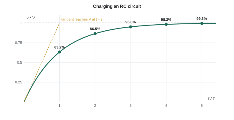
Consider a capacitor C charged through a resistor R from a source that steps from one voltage to another at t = 0. KCL at the capacitor node says the current through R equals the current into C. Substituting Ohm's law and the capacitor equation gives a first-order differential equation whose solution is an exponential approach from the initial voltage to the final voltage. The time constant τ = RC sets the speed: after one time constant the capacitor has covered 63.2 percent of the distance, after three about 95 percent and after five more than 99 percent.
The same form describes every first-order transient, for any voltage or current in the circuit: final value plus the initial difference decaying exponentially. That gives a three-step recipe that avoids solving differential equations. Find the initial value just after the change, using the fact that a capacitor's voltage cannot jump. Find the final value by treating the capacitor as an open circuit in the new DC steady state. Find the time constant as the Thévenin resistance seen by the capacitor multiplied by C. Then write the answer.
Time to reach a threshold
Digital designers usually need not the whole curve but the time at which the voltage crosses a logic threshold. Solving the exponential for t gives a formula used constantly: the time to go from v(0) to a threshold V_th, heading toward V∞, is τ times the natural logarithm of the starting gap divided by the remaining gap at the threshold.
Two special cases are worth remembering. Charging from 0 toward V, the time to reach half of V is τ ln 2 ≈ 0.69τ. The 10-to-90 percent rise time, the usual definition of an edge's speed, is τ ln 9 ≈ 2.2τ. For the I²C bus, whose specification measures rise time from 30 to 70 percent of the supply, the factor is ln(7/3) ≈ 0.847.
Gate delay and edge rates
A logic output driving an input behaves like a voltage source with output resistance R_out, lesson 6's Thévenin equivalent, charging the input capacitance plus the capacitance of the trace. A microcontroller pin with 30 Ω of output resistance driving 15 pF has a time constant of only 0.45 ns, so its edge rises in about 1 ns, which is part of the reason fast edges cause the ringing in lesson 10. Inside a chip, transistors with much higher resistance drive femtofarads of capacitance, and the same RC product sets each gate's propagation delay. Faster logic comes from lowering R or C, which is what shrinking transistors achieves.
Worked problem
The I²C pull-up upper bound
Lesson 3 found that the NS-4's I²C pull-ups must be at least 967 Ω. The bus has about 120 pF of capacitance from the devices, traces and a short cable, and runs in fast mode, which allows a maximum rise time of 300 ns measured from 30 to 70 percent. Find the largest allowed pull-up resistance.
Show solution
- \[t_r = 0.847\,R_pC_b \le 300\ \text{ns}\]
- \[R_p \le \frac{300 \times 10^{-9}}{0.847 \times 120 \times 10^{-12}} = 2.95\ \text{k}\Omega\]
Answer: The pull-up must lie between 967 Ω and 2.95 kΩ. The board's 2.2 kΩ pull-ups give a rise time of 0.847 × 2200 × 120 pF = 224 ns, inside the limit. If a longer cable raised the capacitance to 200 pF, the same resistors would give 373 ns and fail fast mode, and the bus would have to slow to standard mode, which allows 1000 ns.
Debouncing a push button
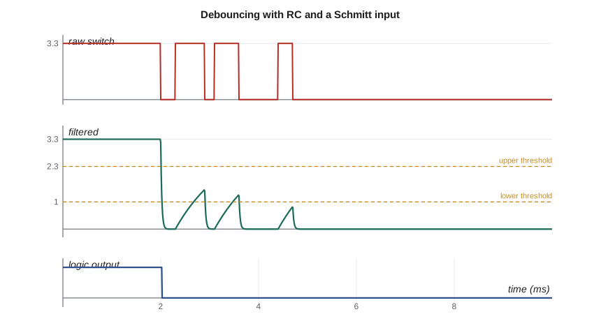
Mechanical switch contacts do not close cleanly. They bounce, making and breaking contact several times over a few milliseconds, and a fast digital input sees each bounce as a separate press. The NS-4's service button bounces for up to about 5 ms. One hardware cure adds an RC filter: the pull-up resistor and a capacitor slow the line so that brief bounces cannot pull it across the threshold, and a Schmitt-trigger input, with its two thresholds from lesson 7, turns the slow edge back into a clean one. Firmware can also debounce by sampling the pin and requiring several consistent readings, and many designs use both.
Worked problem
Choosing the debounce capacitor
The button connects the pin to ground through a 1 kΩ series resistor when pressed, and the 47 kΩ pull-up recharges the line when it opens. The Schmitt input switches low below 1.0 V and high above 2.3 V. Choose a capacitor so that the line, once it has started rising during a bounce from near 0 V, cannot reach 2.3 V within a 1 ms bounce opening, and find the delay before a real release is recognized.
Show solution
- While open, the line charges through 47 kΩ toward 3.3 V from about 0 V.
- \[t = \tau\ln\frac{3.3 - 0}{3.3 - 2.3} = 1.194\,\tau \ \ge 1\ \text{ms} \;\Rightarrow\; \tau \ge 0.84\ \text{ms}\]
- \[C \ge \frac{0.84\ \text{ms}}{47\ \text{k}\Omega} = 17.8\ \text{nF} \;\Rightarrow\; \text{choose } 22\ \text{nF}\]
- \[\tau = 47\ \text{k}\Omega \times 22\ \text{nF} = 1.03\ \text{ms}, \qquad t_{release} = 1.194 \times 1.03 = 1.23\ \text{ms}\]
- Pressing discharges the capacitor through 1 kΩ, τ = 22 µs, so a press is recognized within about 26 µs.
Answer: A 22 nF capacitor rejects bounce openings up to about 1.2 ms and delays recognition of a release by the same amount, imperceptible to a technician. The 1 kΩ series resistor limits the discharge current through the switch contacts to 3.3 mA, which protects them from the capacitor's stored charge.
# Simulate a bouncing switch through the RC debounce filter and a Schmitt input
import math

R_up, R_dn, C = 47e3, 1e3, 22e-9
V_DD, V_TL, V_TH = 3.3, 1.0, 2.3
dt = 1e-6                                   # 1 us steps

# contact state over time: open (False) / closed (True), with bounces when pressed at 2 ms
bounces = [(0.0, False), (2.0e-3, True), (2.3e-3, False), (2.9e-3, True), (3.1e-3, False),
           (3.6e-3, True), (4.4e-3, False), (4.7e-3, True)]   # finally closed at 4.7 ms
def closed(t):
    state = False
    for t0, s in bounces:
        if t >= t0:
            state = s
    return state

v, out, edges, v_peak = V_DD, 1, [], 0.0
raw_prev, raw_edges = False, 0
for k in range(int(10e-3 / dt)):
    t = k * dt
    c = closed(t)
    if c != raw_prev:
        raw_edges += 1
        raw_prev = c
    target, R = (0.0, R_dn) if c else (V_DD, R_up)
    v = target + (v - target) * math.exp(-dt / (R * C))   # exact step of the RC response
    if out == 1 and v < V_TL:
        out = 0; edges.append(t)
    elif out == 0 and v > V_TH:
        out = 1; edges.append(t)
    if edges and v > v_peak:
        v_peak = v
print("raw contact changes: %d" % raw_edges)
print("clean output edges: %d at %s ms" % (len(edges), ", ".join("%.3f" % (e * 1e3) for e in edges)))
print("highest voltage during the bounce openings: %.2f V (upper threshold %.1f V)" % (v_peak, V_TH))raw contact changes: 7 clean output edges: 1 at 2.026 ms highest voltage during the bounce openings: 1.45 V (upper threshold 2.3 V)
The simulation shows seven changes of the raw contact but a single clean output edge, about 0.03 ms after the first contact, and the filtered voltage never climbs above about 1.5 V during the bounces. During each bounce opening the filtered voltage climbs only part of the way back toward the upper threshold before the next closure pulls it down again.
The RL circuit
An inductor in series with a resistor behaves the same way with current in place of voltage. When a voltage is applied, the current rises exponentially toward V/R with time constant τ = L/R; when the source is removed and the current is given a path, such as through a flyback diode, it decays with the time constant of that path. The relay that switches the NS-4's radar has a coil of 50 mH and 300 Ω, so τ = 0.17 ms, and its current reaches 99 percent of its final 40 mA in about 0.8 ms. The relay's armature then takes a few more milliseconds to move, which is why firmware waits 10 ms after energizing it before starting the radar.
Settling and sampling
Lesson 6 calculated how long the ADC's sampling capacitor needs to settle through the battery divider: to reach 12-bit accuracy, the voltage must close all but one part in 4096 of the gap, which takes ln 4096 ≈ 8.3 time constants. The same reasoning applies to any measurement that follows a change: after switching a multiplexer, enabling a sensor's power or changing a gain, wait enough time constants for the error to fall below the resolution you need. Ten-bit accuracy needs 6.9τ, 12-bit 8.3τ and 16-bit 11.1τ.
Measuring a time constant on the bench
Jonah checked the debounce network on a real NS-4 board before trusting the numbers. The simplest method uses an oscilloscope on the capacitor node: release the button, trigger on the rising edge, and read the time at which the voltage reaches 63 percent of its final value. With a 3.3 V rail that is about 2.09 V, and on the bench board it arrived after 1.05 ms, within a few percent of the calculated 1.03 ms. A second method is less sensitive to where the edge starts: measure the 10–90 percent rise time and divide by 2.2, because ln 9 ≈ 2.2. Jonah measured 2.31 ms, giving τ ≈ 1.05 ms again. Agreement between the two methods is a useful check that the waveform really is a single exponential; if they disagree, a second time constant or a nonlinear element, such as a protection diode or a leaky input, is involved. The probe itself adds about 10 pF and 10 MΩ, negligible against 22 nF and 47 kΩ, but on a node with a few picofarads of capacitance, such as an I²C line with a weak pull-up, the probe can slow the edge it is trying to measure. In that case a low-capacitance active probe, or calculating from the measured rise time with the probe capacitance added to the bus capacitance, gives the true figure.
Common mistakes
MistakeAssuming a capacitor's voltage can jump when a switch changes.
InsteadCapacitor voltage and inductor current are continuous; use the value just before the switch as the initial condition.
MistakeUsing the wrong resistance in the time constant.
InsteadUse the Thévenin resistance seen by the capacitor or inductor in the circuit after the change.
MistakeTreating 'five time constants' as exactly finished.
InsteadAfter 5τ the error is 0.7 percent; precision measurements need more, such as 8.3τ for 12 bits.
MistakeDebouncing without a Schmitt input.
InsteadA slow RC edge into a normal input can cause multiple transitions; use a Schmitt-trigger input or firmware filtering.
MistakeChoosing I²C pull-ups only by the minimum value.
InsteadCheck the rise time against the bus capacitance; the upper bound often decides the value.
Summary and key terms
- First-order transients follow x(t) = x∞ + (x(0⁺) − x∞)e^(−t/τ), with τ = R_Th C or L/R_Th.
- Find the initial value from continuity, the final value from the DC steady state, and τ from the Thévenin resistance.
- The time to reach a threshold is τ ln[(V∞ − v(0))/(V∞ − V_th)]; the 10–90 percent rise time is 2.2τ.
- Pull-up rise times bound the resistor value on open-drain buses; RC filters with Schmitt inputs debounce switches.
- Accurate sampling requires waiting many time constants: about 8.3τ for 12-bit accuracy.
- Time constant
- The product RC or ratio L/R that sets the speed of a first-order circuit.
- First-order circuit
- A circuit whose behavior is described by a first-order differential equation, with one effective energy-storage element.
- Rise time
- The time for a signal to go from 10 to 90 percent of its transition, about 2.2τ for an RC circuit.
- Propagation delay
- The time between an input change and the resulting output change of a logic gate.
- Contact bounce
- The rapid making and breaking of a mechanical switch as it closes or opens.
- Settling time
- The time for a response to come within a stated error band of its final value.
Practice problems
Work each problem on paper first, then reveal the answer to check.
Find the time constant of 10 kΩ and 1 µF, and the voltage after 20 ms when charging from 0 toward 5 V.
Show answer
τ = 10 ms; v = 5(1 − e⁻²) ≈ 4.32 V.
How long does an RC circuit charging from 0 take to reach 90 percent?
Show answer
τ ln 10 ≈ 2.3τ.
An I²C bus has 50 pF and 4.7 kΩ pull-ups. What is the 30–70 percent rise time?
Show answer
0.847 × 4.7 kΩ × 50 pF ≈ 199 ns.
An inductor of 10 mH in series with 100 Ω is connected to 5 V. What is the final current and the time constant?
Show answer
50 mA; 0.1 ms.
How many time constants are needed for 10-bit settling?
Show answer
ln 1024 ≈ 6.9.
Lesson quiz · 5 questions
Score 60% or more to complete this lesson.
Create a free account to save your progress, take quizzes and earn a certificate.