
CMP-240 · Lesson 1 of 12 · 22 min
Charge, current, voltage, power and the circuit model
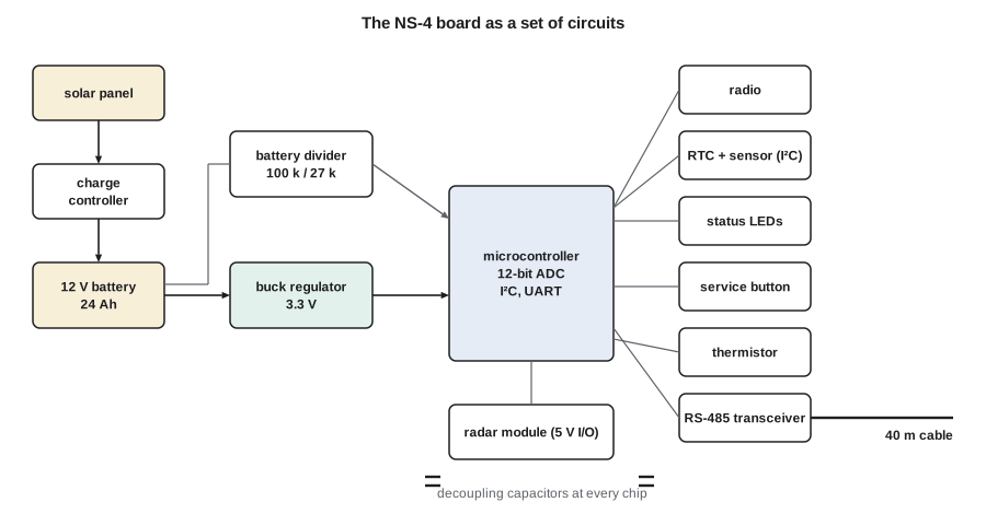
Northway Sensing in Ann Arbor, Michigan, builds the NS-4 roadside traffic counter, a weatherproof sensor node bolted to a pole beside the road. In CMP-200 you met its firmware, and in CMP-220 the server software that collects its data. This course opens the enclosure and looks at the circuit board inside. Every NS-4 runs from a 12 V battery charged by a small solar panel. A buck regulator turns the battery voltage into the 3.3 V that the microcontroller, the radar module and the radio need. Around the microcontroller sit pull-up resistors, status LEDs, a service push button, a voltage divider that lets firmware read the battery, a thermistor for temperature, decoupling capacitors beside every chip and a long RS-485 cable to the roadside cabinet. Each of those parts obeys the circuit laws in this course.
Jonah Abara, the sophomore co-op student who worked on the firmware and the server, has moved to the hardware bench for his summer work term. His supervisor is Ines Carvalho, PE, who designed the current board and is starting the next revision, the NS-5. Maren Holt, the firmware lead, still drops by whenever a hardware change affects her code. Jonah's first task sounds simple: Ines wants the NS-5 to run three weeks without sun instead of two, and she asks him to find out where the energy goes.
Computer engineers meet circuits from a particular angle. Electrical engineering students take two full courses on circuit analysis, ELE-202 and ELE-203, that cover power systems, three-phase circuits and transformers in depth. This course covers the same laws in one term, but every example comes from the hardware that computers and embedded systems are made of: logic outputs driving inputs, pull-up resistors, LEDs, sensors, supply rails, clock edges, decoupling and signal lines. By the end you will be able to read the schematic of a microcontroller board, predict its voltages and currents, choose resistor and capacitor values, estimate timing and recognize the analog effects that make digital circuits misbehave.
Charge and current
Electric charge is the property of matter that makes particles attract or repel one another. It is measured in coulombs (C). An electron carries a charge of about −1.602 × 10⁻¹⁹ C, so one coulomb is the charge of about 6.24 × 10¹⁸ electrons. Charge is conserved: it is never created or destroyed, only moved. In metal wires and copper traces the charge carriers are electrons; in semiconductors they are electrons and holes; in a battery's electrolyte they are ions. Circuit analysis rarely needs to know which, because it works with the net flow of charge.
Current is the rate at which charge flows past a point, measured in amperes (A), where one ampere is one coulomb per second. By convention, the direction of current is the direction positive charge would move, from higher to lower potential through a load. Electrons in a wire actually drift the other way, but the convention, set before the electron was discovered, works perfectly for analysis as long as it is used consistently. In schematics an arrow beside a wire marks the reference direction chosen for its current. If the calculation produces a negative number, the current simply flows opposite to the arrow.
Digital hardware works over an enormous range of currents. A microcontroller input pin draws less than a microampere (µA), a sleeping microcontroller perhaps 2 µA, an LED 2 to 10 milliamperes (mA), the radar module about 60 mA while it transmits, and the solar charger up to 1.5 A on a bright afternoon. Engineering prefixes keep these numbers readable: pico (p, 10⁻¹²), nano (n, 10⁻⁹), micro (µ, 10⁻⁶), milli (m, 10⁻³), kilo (k, 10³), mega (M, 10⁶) and giga (G, 10⁹). Writing 4.7 kΩ or 100 nF is clearer and less error-prone than 4700 Ω or 0.0000001 F, and datasheets use these prefixes throughout.
Battery capacity is usually given as a charge in ampere-hours (Ah) or milliampere-hours (mAh). One ampere-hour is the charge delivered by 1 A for one hour, or 3600 C. The NS-4's battery is rated 24 Ah, so in principle it could supply 1 A for 24 hours or 24 mA for 1000 hours. Real batteries deliver less at high currents and low temperatures, and lead-acid and lithium iron phosphate cells both last longer if they are not fully discharged every time, so designers plan to use only part of the rated capacity.
Voltage
Voltage is the energy per unit charge gained or lost when charge moves between two points, measured in volts (V), where one volt is one joule per coulomb. It is always a difference between two points, even when only one point is named. When a schematic says a node is at 3.3 V, it means 3.3 V above the reference node called ground, marked with the ground symbol. Ground in a circuit is simply the agreed zero of potential; it need not be connected to the earth, and on the NS-4 it is the battery's negative terminal.
A battery or regulator raises the potential of charge passing through it; a resistor, LED or chip lowers it, turning electrical energy into heat, light or computation. Voltage is labeled with a + and a − sign at the two terminals of an element. The + terminal is the one assumed to be at higher potential; as with current, a negative answer just means the polarity is the other way round. The double-subscript notation v_ab means the voltage of point a measured relative to point b, so v_ab = −v_ba.
Digital logic gives voltages meaning. In a 3.3 V logic family, an output near 0 V represents a logic 0 and an output near 3.3 V a logic 1, and the datasheet specifies how close to each rail the output must be and what input voltages are guaranteed to be read correctly. Those thresholds are analog quantities, set by circuits made of transistors, and much of this course is about keeping real voltages inside them despite loading, noise and timing.
Power and energy
Power is the rate at which energy is delivered or absorbed, measured in watts (W), one joule per second. For any two-terminal element, the power is the product of the voltage across it and the current through it. To decide whether the element absorbs or delivers power, circuit analysis uses the passive sign convention: if the reference current enters the element at its + terminal, then p = vi is the power absorbed. A positive result means the element absorbs energy, as a resistor always does. A negative result means it delivers energy to the rest of the circuit, as a battery does when it discharges.
Conservation of energy means that in any circuit, at every instant, the total power absorbed by all elements is zero: the power delivered by sources equals the power absorbed by everything else. This is a useful check on any analysis. If the battery delivers 0.54 W, the regulator, chips, LEDs and resistors together must absorb exactly 0.54 W.
Energy is power integrated over time. Battery-powered designers work in watt-hours (Wh) or milliwatt-hours. The energy stored in a battery is roughly its charge capacity multiplied by its average voltage, so the NS-4's 24 Ah battery at about 12.8 V holds around 300 Wh. If the board's average power is 0.6 W, a full battery lasts about 500 hours, or three weeks, before it is completely empty. In practice only part of that is usable.
Ideal sources and elements
Circuit analysis replaces physical parts with idealized models. An ideal voltage source keeps a fixed voltage between its terminals whatever current flows; an ideal current source keeps a fixed current whatever voltage appears across it. Real sources only approximate these: a battery's voltage sags as current rises because of its internal resistance, and a regulator holds its output only up to its rated current. Later lessons model those limitations by adding resistance to the ideal source.
Dependent, or controlled, sources have a value that depends on a voltage or current elsewhere in the circuit. They do not correspond to a single physical part but model the behavior of transistors and amplifiers: an op-amp, for example, can be modeled as a voltage source whose value is a large gain multiplied by the difference between its inputs. Lesson 7 uses this model.
The passive elements are the resistor, which dissipates energy as heat, the capacitor, which stores energy in an electric field, and the inductor, which stores energy in a magnetic field. With sources, these three elements model almost everything on a board as long as the circuit is small compared with the wavelength of the signals in it. That condition is called the lumped-element assumption, and it means the voltage and current are the same everywhere along a wire at a given instant. At the NS-4's frequencies the assumption holds for the board itself, but lesson 10 shows where it begins to fail on long cables and fast clock edges.
Nodes, branches and loops
A circuit is a set of elements connected at their terminals. A node is a point where two or more elements connect; everything joined by ideal wire is the same node, however long the wire looks on the schematic. A branch is a single element or a path between two nodes. A loop is any closed path that starts and ends at the same node without passing through any node twice. These words matter because the two fundamental laws of circuit analysis, introduced in lesson 2, are statements about nodes and loops.
Worked problem
The NS-4 energy budget
Jonah measures the board's current from the 12.8 V battery in each operating state. The node sleeps at 3.2 mA for 70 percent of the time, listens with the radar on at 46 mA for 28 percent, and transmits a radio upload at 210 mA for 2 percent. Find the average current and power, the energy used per day, and how many days a 24 Ah battery lasts if only 60 percent of its capacity may be used.
Show solution
- \[\bar{I} = 0.70(3.2) + 0.28(46) + 0.02(210) = 2.24 + 12.88 + 4.20 = 19.32\ \text{mA}\]
- \[\bar{P} = 12.8\ \text{V} \times 19.32\ \text{mA} = 247\ \text{mW}\]
- \[E_{day} = 0.247\ \text{W} \times 24\ \text{h} = 5.93\ \text{Wh}\]
- \[E_{usable} = 0.60 \times 24\ \text{Ah} \times 12.8\ \text{V} = 184\ \text{Wh}\]
- \[t = \frac{184}{5.93} \approx 31\ \text{days}\]
Answer: The board averages about 19 mA, or 0.25 W, and uses about 5.9 Wh a day, so the usable battery lasts about 31 days. The radar listening state uses two thirds of the energy even though the radio's 210 mA bursts look more alarming. Ines's three-week target is met on paper, but the cold-weather capacity and the charger's own losses still have to be added.
The example shows the most important habit in low-power design: weight each current by the time spent at it. Peaks determine the size of the regulator and the wires; averages determine the battery. Engineers who look only at peak currents often optimize the wrong thing, here the radio, when the real gain is in reducing the radar's listening duty cycle.
# NS-4 power budget: average current, daily energy and battery life
states = [            # (name, current in mA, fraction of time)
    ("sleep", 3.2, 0.70),
    ("radar listen", 46.0, 0.28),
    ("radio upload", 210.0, 0.02),
]
V_batt = 12.8                    # volts
capacity_Ah = 24.0
usable = 0.60                    # fraction of capacity we allow ourselves to use

I_avg = sum(i * f for _, i, f in states)
for name, i, f in states:
    share = i * f / I_avg
    print("%-13s %6.1f mA x %4.0f%%  -> %5.2f mA (%4.1f%% of energy)" % (name, i, f * 100, i * f, share * 100))
P_avg = V_batt * I_avg / 1000     # watts
E_day = P_avg * 24                # Wh per day
E_use = usable * capacity_Ah * V_batt
print("average current %.2f mA, average power %.0f mW" % (I_avg, P_avg * 1000))
print("energy per day %.2f Wh; usable battery %.0f Wh; life %.1f days" % (E_day, E_use, E_use / E_day))

# What if the radar listened only 20% of the time (sleeping the rest)?
I_new = 0.78 * 3.2 + 0.20 * 46 + 0.02 * 210
print("with 20%% radar duty: %.2f mA -> %.1f days" % (I_new, E_use / (V_batt * I_new / 1000 * 24)))sleep 3.2 mA x 70% -> 2.24 mA (11.6% of energy) radar listen 46.0 mA x 28% -> 12.88 mA (66.7% of energy) radio upload 210.0 mA x 2% -> 4.20 mA (21.7% of energy) average current 19.32 mA, average power 247 mW energy per day 5.94 Wh; usable battery 184 Wh; life 31.1 days with 20% radar duty: 15.90 mA -> 37.7 days
Cutting the radar's listening time from 28 to 20 percent extends the life by about a third. Maren points out that the firmware already knows when traffic is light, overnight for example, so a smarter schedule is a software change with a hardware payoff. This kind of trade between hardware and software is exactly where computer engineers are most useful.
Safety on the bench
Most digital hardware runs at low voltages that cannot drive a dangerous current through dry skin, but low voltage is not the same as safe. A 12 V battery like the NS-4's can deliver hundreds of amperes into a short circuit, enough to make a wrench or ring glow red, melt traces and start a fire, which is why every battery lead on the board has a fuse close to the terminal. Large capacitors can hold a charge after power is removed. Mains-powered bench equipment carries lethal voltages inside. The habits from ELE-280's lab safety lesson apply here too: remove power before changing connections, never wear rings or watches near a battery, and check a capacitor is discharged before touching it.
Common mistakes
MistakeThinking current is used up as it flows through a component.
InsteadCharge is conserved: the current entering an element equals the current leaving it. Energy is what the element converts.
MistakeQuoting a voltage at a single point without a reference.
InsteadVoltage is always between two points; a node voltage is measured relative to the chosen ground.
MistakeAdding power in milliwatts to power in watts, or current in µA to current in mA.
InsteadConvert to one unit, or carry the prefixes explicitly, before adding.
MistakeSizing a battery from peak current.
InsteadBattery life depends on average current, each state's current weighted by its fraction of time.
MistakeGetting the sign of power wrong for a source.
InsteadWith the passive sign convention, p = vi is absorbed power; a source delivering energy shows a negative value.
Summary and key terms
- Current is the rate of flow of charge (1 A = 1 C/s); its reference direction is the direction positive charge would move.
- Voltage is the energy per unit charge between two points (1 V = 1 J/C); node voltages are measured relative to ground.
- Power is p = vi; with the passive sign convention it is the power absorbed, and the total power in a circuit sums to zero.
- Energy is power integrated over time; battery life depends on average power, not peak power.
- Ideal sources, resistors, capacitors and inductors model circuits that are small compared with signal wavelengths (the lumped-element assumption).
- Coulomb
- The SI unit of charge, about the charge of 6.24 × 10¹⁸ electrons.
- Ampere
- The SI unit of current, one coulomb per second.
- Volt
- The SI unit of voltage, one joule per coulomb.
- Ground
- The reference node of a circuit, defined as 0 V.
- Passive sign convention
- Choosing the current reference to enter an element's + terminal, so that p = vi is the power absorbed.
- Duty cycle
- The fraction of time a circuit spends in a particular state, such as transmitting or switched on.
- Lumped-element model
- A model in which voltages and currents are the same everywhere along a connection at a given instant.
Practice problems
Work each problem on paper first, then reveal the answer to check.
A sensor draws 1.8 mA for 5 ms every second and 4 µA the rest of the time. What is its average current?
Show answer
0.005(1.8 mA) + 0.995(0.004 mA) ≈ 9.0 + 4.0 = 13.0 µA.
How many coulombs does a 2000 mAh cell hold?
Show answer
2 Ah × 3600 s/h = 7200 C.
An LED has 2.0 V across it and 8 mA through it, entering its + terminal. What power does it absorb?
Show answer
p = 2.0 × 0.008 = 16 mW, absorbed.
A battery shows 12.6 V across it and 0.5 A leaving its + terminal into the circuit. What is its absorbed power using the passive sign convention?
Show answer
The current enters the − terminal, so absorbed power is −6.3 W; it delivers 6.3 W.
Why can the voltage at a node be given as a single number?
Show answer
Because it is measured relative to the ground node, which is defined as 0 V.
Lesson quiz · 5 questions
Score 60% or more to complete this lesson.
Create a free account to save your progress, take quizzes and earn a certificate.