
CMP-240 · Lesson 6 of 12 · 22 min
Thévenin and Norton equivalents and loading
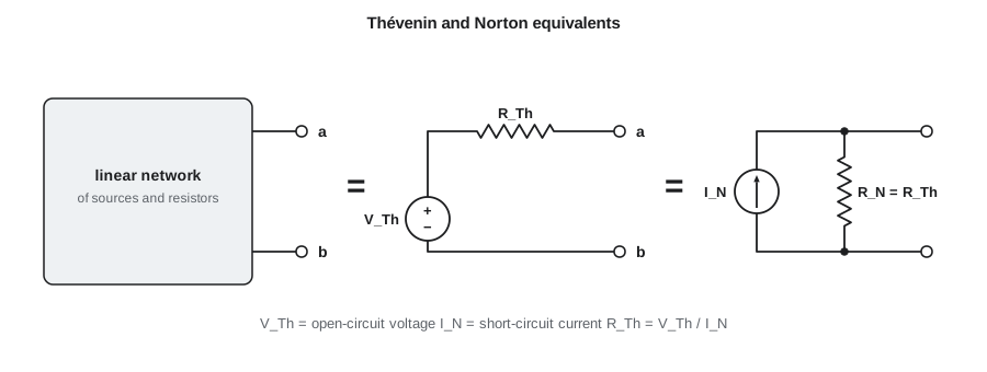
When one part of a circuit drives another, what matters is how the driving side behaves at the connection, not every detail inside it. Thévenin's theorem says that any linear circuit, seen from two terminals, behaves exactly like a single voltage source in series with a single resistor. Norton's theorem says the same circuit also behaves like a current source in parallel with a resistor. These equivalents turn complicated networks into something you can reason about at a glance, and they are the right tool for the question computer engineers ask constantly: what happens when I connect this output to that input?
Jonah now understands the battery divider's leakage problem, but Maren raises a new one. Firmware samples the divider with the microcontroller's ADC, which briefly connects a small internal capacitor to the pin at the start of each conversion. She has noticed that the first reading after waking is always low. To explain it, Jonah needs to know how stiff the divider is as a source, and that is exactly what a Thévenin equivalent tells him.
Thévenin's theorem
Take any linear network of resistors and sources and pick two terminals, a and b. Seen from those terminals, the network is equivalent to an ideal voltage source V_Th in series with a resistance R_Th. The Thévenin voltage V_Th is the open-circuit voltage between a and b, the voltage you would measure with nothing connected. The Thévenin resistance R_Th is the resistance seen looking back into the terminals with every independent source turned off, voltage sources shorted and current sources opened.
Once you have the equivalent, connecting any load R_L is just a voltage divider. That is the power of the theorem: you analyze the complicated network once, and then the effect of every possible load follows from a single formula. Engineers summarize the same idea informally by talking about the output resistance of a driving circuit and the input resistance of a receiving circuit.
Worked problem
The battery divider as a source
The battery divider connects a 12.8 V battery through R1 = 100 kΩ to the ADC node and R2 = 27 kΩ from that node to ground. Find the Thévenin equivalent seen by the ADC pin.
Show solution
- Open-circuit voltage, by the divider rule:
- \[V_{Th} = 12.8 \times \frac{27}{100 + 27} = 2.721\ \text{V}\]
- Turn off the battery (short it). Looking into the ADC node, R1 and R2 are in parallel:
- \[R_{Th} = \frac{100 \times 27}{100 + 27} = 21.26\ \text{k}\Omega\]
Answer: The ADC pin sees a 2.72 V source behind 21.3 kΩ. Any load on the pin forms a divider with that 21.3 kΩ: the 200 kΩ leak from lesson 2 gives 2.72 × 200/221.3 = 2.46 V, matching the long calculation in one line.
Norton's theorem and source transformation
The Norton equivalent replaces the same network with a current source I_N in parallel with a resistance R_N. The Norton current is the current that flows through a short circuit placed across the terminals, and the Norton resistance equals the Thévenin resistance. The two equivalents are related by Ohm's law, so converting between them is a one-line calculation called a source transformation.
Source transformations are useful both ways. In nodal analysis it is convenient to turn voltage sources in series with resistors into current sources, as lesson 4 did with the 3.3 V source and its 10 kΩ resistor. In mesh analysis the reverse transformation is convenient. Some real devices are also more naturally described as current sources: a photodiode produces a current proportional to light, and a battery charger in its current-limited mode delivers a fixed current regardless of the battery voltage.
Finding R_Th with dependent sources, or by measurement
When a network contains dependent sources, R_Th cannot be found by simply combining resistors, because the dependent sources stay active. Instead, turn off the independent sources, apply a test voltage v_t across the terminals, calculate the current i_t it delivers, and take R_Th = v_t/i_t. Another general method uses the two measurements that define the equivalents: R_Th = V_oc / I_sc, the open-circuit voltage divided by the short-circuit current.
The same two-measurement idea works on a real circuit at the bench, with one caution. Shorting the output of a regulator or a logic gate may damage it or trigger its current limit, so engineers usually load the output with a known resistor instead. If the open-circuit voltage is V_oc and the voltage drops to v_L with a load R_L connected, then R_Th = R_L (V_oc − v_L)/v_L, which follows from the divider formula. Jonah uses this method on a spare microcontroller pin in the example below.
Worked problem
Measuring a logic output's resistance
Jonah sets a spare 3.3 V microcontroller pin high. With no load his meter reads 3.300 V; with a 470 Ω resistor to ground it reads 3.105 V. Find the pin's Thévenin resistance, and predict its voltage when driving the 270 Ω resistor of an LED circuit whose LED is removed.
Show solution
- \[R_{Th} = 470 \times \frac{3.300 - 3.105}{3.105} = 470 \times 0.0628 = 29.5\ \Omega\]
- \[v_{270} = 3.3 \times \frac{270}{29.5 + 270} = 2.975\ \text{V}\]
Answer: The pin behaves like a 3.3 V source with about 30 Ω of output resistance, close to the 25 Ω value assumed in lesson 2. Driving 270 Ω it sags to about 2.98 V, still a valid logic high but lower than the rail. Output resistance is why datasheets specify V_OH at a stated load current rather than as a single number.
Loading
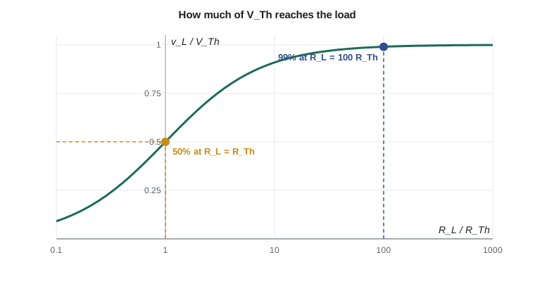
Loading is the change in a circuit's output when something is connected to it. A source with a low Thévenin resistance is called stiff, because its voltage barely changes when loaded; a source with a high Thévenin resistance is soft. The fractional drop is R_Th/(R_Th + R_L), so the load resistance must be much larger than the source resistance for the drop to be small. A ratio of 100 to 1 keeps the drop near one percent.
Logic families use this idea to define fan-out, the number of inputs one output can drive. Each CMOS input draws almost no steady current, so in a steady state one output could in principle drive hundreds of inputs. The real limits come from leakage, which adds up across many inputs, and from capacitance, which slows every edge, as lesson 9 shows. Older bipolar logic families drew real input current and had fan-out limits of about ten, which is where the term began.
The ADC sampling problem
A successive-approximation ADC, the kind in most microcontrollers, does not draw a steady current. At the start of each conversion it connects an internal sampling capacitor, perhaps 10 pF, to the pin through a switch, and the capacitor must charge to the pin voltage within the sampling time. The capacitor charges through the source's Thévenin resistance plus the switch resistance, and lesson 9 shows that it gets within one least-significant bit of a 12-bit converter only after about 8.3 time constants. With R_Th = 21.3 kΩ plus about 1 kΩ of switch resistance and 10 pF, one time constant is about 220 ns and 8.3 of them take about 1.8 µs, longer than the 0.5 µs sampling time Maren's firmware uses. That is why the first reading is low: the capacitor has not finished charging.
There are three common fixes. Firmware can lengthen the sampling time, which most microcontrollers allow. The designer can lower the divider's resistance, at the cost of more battery current. Or the designer can place a capacitor of about 100 nF from the ADC pin to ground, which holds the divider's voltage like a small reservoir; when the sampling capacitor connects, it takes its charge from the 100 nF capacitor, which drops by only 10/100,000 of its voltage. Ines chooses the capacitor, and lesson 8 explains why it works.
Maximum power transfer
A related result says that a source delivers the most power to a load when the load resistance equals the source's Thévenin resistance. At that point the load receives V_Th²/(4R_Th) and the same power is wasted in the source, so the efficiency is only 50 percent. Matching for maximum power is important in radio-frequency circuits and antennas, where signals are weak and every microwatt counts, and in the matched terminations of lesson 10. It is the wrong goal for power supplies and batteries, where you want the load resistance much larger than the source resistance so that little power is lost inside the source.
# Thevenin equivalents: from component values, and from two bench measurements
def par(a, b):
    return a * b / (a + b)

# 1. The battery divider seen from the ADC pin
V_batt, R1, R2 = 12.8, 100e3, 27e3
V_th = V_batt * R2 / (R1 + R2)
R_th = par(R1, R2)
print("divider: V_th = %.3f V, R_th = %.2f kohm" % (V_th, R_th / 1e3))
for RL in (1e9, 10e6, 1e6, 200e3, 100e3):
    print("  load %8.0f kohm -> %.3f V" % (RL / 1e3, V_th * RL / (R_th + RL)))

# 2. A logic pin measured open and with a 470 ohm load
V_oc, V_loaded, R_test = 3.300, 3.105, 470.0
R_out = R_test * (V_oc - V_loaded) / V_loaded
print("logic pin: R_out = %.1f ohm" % R_out)

# 3. How long the ADC's 10 pF sampling capacitor needs, in time constants, for 12-bit accuracy
import math
n_tau = math.log(2 ** 12)          # settle to within 1 part in 4096 (about one LSB)
tau = (R_th + 1e3) * 10e-12        # Thevenin resistance plus about 1 kohm of switch resistance
print("need %.1f time constants = %.2f us of sampling time" % (n_tau, n_tau * tau * 1e6))divider: V_th = 2.721 V, R_th = 21.26 kohm load 1000000 kohm -> 2.721 V load 10000 kohm -> 2.715 V load 1000 kohm -> 2.665 V load 200 kohm -> 2.460 V load 100 kohm -> 2.244 V logic pin: R_out = 29.5 ohm need 8.3 time constants = 1.85 us of sampling time
The output confirms the two practical lessons. Loads of 10 MΩ or more barely disturb the divider, a 1 MΩ load already pulls it down by 2 percent, and anything near 100 kΩ pulls it down badly. And without the reservoir capacitor, the ADC would need nearly 2 µs of sampling time to read the divider to 12-bit accuracy.
Common mistakes
MistakeFinding R_Th with the independent sources still active.
InsteadShort voltage sources and open current sources before combining resistances, or use the test-source method.
MistakeShorting a real logic output or regulator to measure I_sc.
InsteadLoad it with a known resistor and calculate R_Th from the voltage drop.
MistakeDesigning a battery-powered circuit for maximum power transfer.
InsteadMaximum power transfer wastes half the power; for efficiency make R_L much larger than R_Th.
MistakeAssuming an ADC input draws no current at all.
InsteadIts sampling capacitor draws a burst of charge; the source must settle within the sampling time.
MistakeForgetting that R_N equals R_Th.
InsteadThe Norton and Thévenin equivalents of one network share the same resistance.
Summary and key terms
- Any linear two-terminal network is equivalent to V_Th in series with R_Th, or to I_N in parallel with R_N = R_Th.
- V_Th is the open-circuit voltage, I_N the short-circuit current, and R_Th the resistance with independent sources off, or V_oc/I_sc.
- A load sees a divider: v_L = V_Th R_L/(R_Th + R_L); stiff sources have low R_Th.
- Logic outputs have tens of ohms of output resistance; high-resistance dividers are soft sources.
- Maximum power transfer occurs at R_L = R_Th with only 50 percent efficiency.
- Thévenin equivalent
- A voltage source in series with a resistance that behaves like a given network at two terminals.
- Norton equivalent
- A current source in parallel with a resistance that behaves like a given network at two terminals.
- Output resistance
- The Thévenin resistance of a circuit seen at its output.
- Input resistance
- The resistance a circuit presents at its input to whatever drives it.
- Loading
- The change in a circuit's output caused by connecting a load.
- Fan-out
- The number of logic inputs one output can drive while meeting its specifications.
- Maximum power transfer
- The condition R_L = R_Th, at which a source delivers the most power to a load.
Practice problems
Work each problem on paper first, then reveal the answer to check.
A sensor's open-circuit output is 1.8 V and falls to 1.5 V with a 10 kΩ load. Find R_Th.
Show answer
10 kΩ × (1.8 − 1.5)/1.5 = 2 kΩ.
Convert a 5 V source with 1 kΩ in series into a Norton equivalent.
Show answer
5 mA in parallel with 1 kΩ.
Find R_Th of a divider made from two 10 kΩ resistors across 3.3 V.
Show answer
10 kΩ ∥ 10 kΩ = 5 kΩ, with V_Th = 1.65 V.
What load resistance draws maximum power from a source with R_Th = 50 Ω, and what is the efficiency?
Show answer
50 Ω; 50 percent.
Why does a reservoir capacitor on an ADC pin help a high-resistance divider?
Show answer
It supplies the sampling capacitor's charge quickly, so the high source resistance only has to recharge it slowly between samples.
Lesson quiz · 5 questions
Score 60% or more to complete this lesson.
Create a free account to save your progress, take quizzes and earn a certificate.