
CMP-240 · Lesson 8 of 12 · 25 min
Capacitors, inductors and decoupling
So far every circuit has been made of resistors and sources, and every voltage and current has responded instantly to a change. Real digital hardware is full of elements that store energy and so respond over time. A capacitor stores energy in an electric field and resists sudden changes of voltage; an inductor stores energy in a magnetic field and resists sudden changes of current. Count the parts on the NS-4 board and capacitors outnumber every other component: there are 38 of them, most of them small ceramic decoupling capacitors placed beside the pins of each chip. This lesson explains what they do, and the next two lessons describe how circuits containing them behave in time.
Capacitance
A capacitor is two conductors separated by an insulator, called the dielectric. When a voltage is applied, charge +q collects on one conductor and −q on the other, and the charge is proportional to the voltage. The constant of proportionality is the capacitance C, measured in farads (F). A farad is enormous for electronics; board-level capacitors range from a few picofarads (pF) to a few thousand microfarads (µF). For two parallel plates of area A separated by distance d, C = εA/d, where ε is the permittivity of the dielectric, which is why high-permittivity ceramics pack large capacitance into tiny packages.
Differentiating q = Cv gives the capacitor's defining equation: the current is proportional to the rate of change of voltage. Three consequences follow. A capacitor with a constant voltage carries no current, so in a DC steady state it behaves like an open circuit. Its voltage cannot change instantaneously, because that would need infinite current; when a circuit switches, the capacitor's voltage just after the switch equals its voltage just before. And it stores energy ½Cv², which it can return to the circuit later. A large current flowing briefly changes the voltage only a little if C is large, which is exactly the property that decoupling uses.
Capacitors in parallel share the same voltage, and their charges add, so parallel capacitances add like series resistances. Capacitors in series share the same charge, and their voltages add, so series capacitances combine like parallel resistances. The rules are the opposite of the resistor rules, which is easy to check: putting two capacitors side by side in parallel doubles the plate area.
Real capacitors
Multilayer ceramic capacitors (MLCCs) are the workhorse of digital boards: small, cheap, low in internal resistance and able to deliver current very quickly. They come in dielectric classes with very different behavior. Class 1 ceramics such as C0G (also called NP0) hold their value almost perfectly over temperature and voltage but only reach a few nanofarads in small packages, so they are used for timing and filters. Class 2 ceramics such as X7R and X5R reach tens of microfarads but lose capacitance with temperature and, more surprisingly, with applied DC voltage. A 10 µF X5R capacitor rated 10 V in an 0603 package may have only 4 µF left at 3.3 V. Designers must read the manufacturer's DC bias curve rather than trusting the marked value.
Electrolytic capacitors, aluminum or polymer, provide hundreds or thousands of microfarads for bulk energy storage at the cost of size, higher internal resistance and, for wet aluminum types, a limited life that halves for every 10 °C rise in temperature. The NS-4 uses a 220 µF polymer capacitor where the battery enters the board, sized to ride through the radio's 210 mA bursts. Every real capacitor also has some equivalent series resistance (ESR) and equivalent series inductance (ESL), which matter at high frequencies and are why a decoupling capacitor must sit as close as possible to the pin it serves.
| Type | Typical values | Strengths | Weaknesses | Used on the NS-4 for |
|---|---|---|---|---|
| C0G/NP0 ceramic | 1 pF to 10 nF | Stable, precise, low loss | Small values only | Crystal load capacitors, RC filters |
| X7R/X5R ceramic | 1 nF to 47 µF | Small, low ESR, cheap | Loses capacitance with voltage and temperature | Decoupling, regulator input and output |
| Polymer electrolytic | 10 µF to 1000 µF | High capacitance, low ESR | Larger, more expensive | Battery input bulk capacitor |
| Aluminum electrolytic | 1 µF to 10,000 µF | Cheapest high capacitance | High ESR, limited life when hot | Not used: temperature range too harsh |
Inductance
An inductor is usually a coil of wire, often wound on a magnetic core. Current through it creates a magnetic flux, and the flux linkage is proportional to the current; the constant is the inductance L, measured in henries (H). By Faraday's law a changing flux induces a voltage, so the voltage across an inductor is proportional to the rate of change of its current. The inductor is the capacitor's mirror image: in a DC steady state it behaves like a short circuit, its current cannot change instantaneously, and it stores energy ½Li².
Inductances add in series and combine like resistances in parallel, the same rules as resistors. On a digital board, discrete inductors appear in switching regulators, such as the NS-4's buck converter with its 22 µH inductor, and in filters. Unwanted inductance appears everywhere else: every trace, wire and component lead has some, roughly 1 nH per millimeter for a thin trace or wire. That parasitic inductance is harmless for steady currents but becomes important whenever current changes quickly.
Inductive kickback
Because an inductor's current cannot change instantly, trying to stop it suddenly produces a large voltage. If a transistor switches off the current in a relay coil or a motor winding in a few nanoseconds, the inductor generates whatever voltage is needed to keep the current flowing, often hundreds of volts, and that voltage can destroy the transistor. The standard protection is a flyback diode across the coil, which gives the current a path to circulate and decay gradually. The NS-4 switches power to the radar module with a latching relay, and its driver includes exactly such a diode.
Worked problem
Why the relay needs a diode
The relay coil has 50 mH of inductance and carries 40 mA. Its driver transistor switches off in 20 ns. Estimate the voltage the coil would generate without a flyback diode, and the energy that must go somewhere.
Show solution
- \[v = L\,\frac{\Delta i}{\Delta t} = 0.050 \times \frac{0.040}{20 \times 10^{-9}} = 100{,}000\ \text{V}\]
- \[w = \tfrac{1}{2}Li^2 = \tfrac{1}{2}(0.050)(0.040)^2 = 40\ \mu\text{J}\]
Answer: The ideal calculation gives 100 kV. In reality the transistor breaks down long before that, at perhaps 40 V, and absorbs the 40 µJ in its junction every time the relay switches, until it fails. With a diode across the coil the voltage is clamped to about 0.7 V above the supply and the energy is dissipated harmlessly in the coil's own resistance.
Decoupling
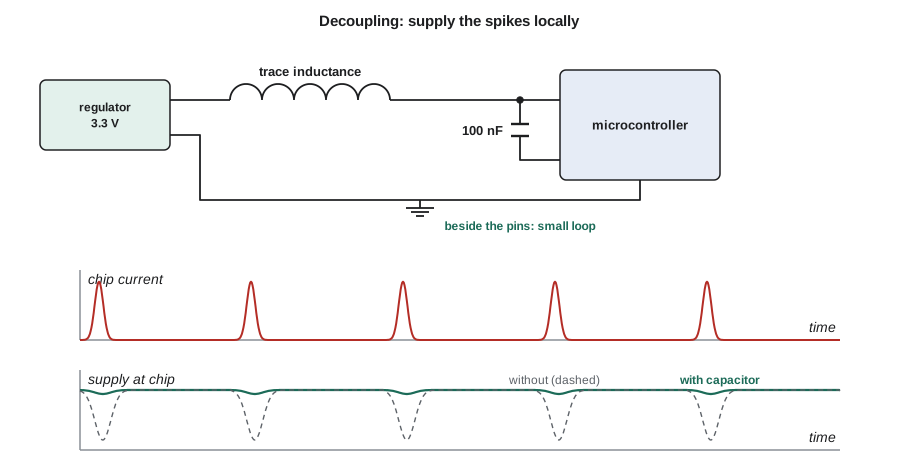
Every CMOS logic chip draws its supply current in short spikes. Each time a gate switches, it briefly charges or discharges the capacitance of the wiring it drives, and a microcontroller switching thousands of gates on each clock edge draws current pulses of tens or hundreds of milliamperes lasting a few nanoseconds. The supply's regulator is too slow and too far away to supply those pulses: the trace from regulator to chip has inductance, and v = L di/dt means a 100 mA change in 2 ns through 10 nH of trace drops 0.5 V. Without help, the chip's supply voltage would dip on every clock edge.
A decoupling capacitor, usually 100 nF of X7R ceramic, placed millimeters from the chip's power pin, supplies those spikes locally. During the spike the capacitor delivers the charge and its voltage falls only a little; between spikes the regulator slowly tops it up. The loop formed by the capacitor, the chip's power pin and the chip's ground pin must be as small as possible, because its inductance is what limits how fast the capacitor can respond. That is why layout guidelines insist on placing decoupling capacitors next to the pins, with short, wide connections and a solid ground plane underneath.
Worked problem
Sizing a decoupling capacitor
On each clock edge the NS-4's microcontroller draws a current spike of about 120 mA for 3 ns from its 3.3 V pin. The supply must not dip by more than 50 mV. Find the minimum capacitance, then allow for the X7R part losing 40 percent of its value at 3.3 V.
Show solution
- The charge drawn in one spike is Δq = IΔt.
- \[\Delta q = 0.120 \times 3 \times 10^{-9} = 0.36\ \text{nC}\]
- \[C \ge \frac{\Delta q}{\Delta v} = \frac{0.36\ \text{nC}}{0.050\ \text{V}} = 7.2\ \text{nF}\]
- \[C_{marked} \ge \frac{7.2\ \text{nF}}{0.60} = 12\ \text{nF}\]
Answer: The calculation asks for at least 12 nF per spike, so the usual 100 nF part has a comfortable margin of about eight times. In practice designers also add a few microfarads near each chip for slower current changes and rely on the regulator's output capacitor for the slowest. The combination of values, each effective over a different range of time, is called a decoupling network.
Charge sharing and the ADC reservoir
Lesson 6 left a promise: a 100 nF capacitor on the ADC pin lets the high-resistance battery divider drive the converter's sampling capacitor. The explanation is charge sharing. When the ADC's switch closes, its 10 pF sampling capacitor, which may hold a different voltage left from the last conversion, is connected in parallel with the 100 nF reservoir. Charge is conserved, so the two settle at a common voltage equal to the total charge divided by the total capacitance. Because the reservoir is ten thousand times larger, the common voltage is almost exactly the reservoir's voltage.
Worked problem
How much does the reservoir droop?
The reservoir capacitor is 100 nF at 2.72 V. The ADC's 10 pF sampling capacitor starts at 0 V in the worst case. Find the reservoir's voltage after charge sharing, and compare the droop with one ADC step of 0.81 mV.
Show solution
- \[v_{final} = \frac{100\ \text{nF} \times 2.72 + 10\ \text{pF} \times 0}{100.01\ \text{nF}} = 2.72 \times 0.99990 = 2.71973\ \text{V}\]
- \[\Delta v = 2.72 - 2.71973 = 0.27\ \text{mV}\]
Answer: The droop is 0.27 mV, about a third of one ADC step, so the reading is accurate to 12 bits even with the worst-case starting voltage. The divider then recharges the reservoir through its 21 kΩ Thévenin resistance before the next sample, which takes about 10 ms if samples are taken once a second, far more time than needed.
# Decoupling and charge-sharing checks for the NS-4
def decouple_C(i_spike, t_spike, dv_max, derate=1.0):
    """Capacitance needed so a current spike droops the rail by at most dv_max."""
    return i_spike * t_spike / dv_max / derate

C = decouple_C(0.120, 3e-9, 0.050, derate=0.60)
print("decoupling: need at least %.1f nF marked value" % (C * 1e9))

def share(c1, v1, c2, v2):
    """Voltage after connecting two charged capacitors in parallel."""
    return (c1 * v1 + c2 * v2) / (c1 + c2)

lsb = 3.3 / 4096
for c_res in (0, 1e-9, 10e-9, 100e-9):
    if c_res == 0:
        print("no reservoir: the sampling capacitor must charge through 21 kohm")
        continue
    v = share(c_res, 2.72, 10e-12, 0.0)
    droop = 2.72 - v
    print("reservoir %5.0f nF: droop %.3f mV = %.2f LSB" % (c_res * 1e9, droop * 1e3, droop / lsb))

# Inductive kickback without a diode
L, i, t_off = 0.050, 0.040, 20e-9
print("relay kickback: %.0f V ideal, energy %.0f uJ" % (L * i / t_off, 0.5 * L * i * i * 1e6))decoupling: need at least 12.0 nF marked value no reservoir: the sampling capacitor must charge through 21 kohm reservoir 1 nF: droop 26.931 mV = 33.43 LSB reservoir 10 nF: droop 2.717 mV = 3.37 LSB reservoir 100 nF: droop 0.272 mV = 0.34 LSB relay kickback: 100000 V ideal, energy 40 uJ
The table of reservoir sizes shows why 100 nF was chosen: 10 nF would droop by about three ADC steps, and 1 nF by about thirty. A few cents of capacitor solves a problem that would otherwise need a buffer amplifier or more battery current.
Common mistakes
MistakeThinking a capacitor passes DC current.
InsteadIn a DC steady state a capacitor is an open circuit; it carries current only while its voltage changes.
MistakeTrusting the marked value of a Class 2 ceramic capacitor.
InsteadCheck the DC bias and temperature curves; the effective value can be less than half the marking.
MistakePlacing decoupling capacitors far from the chip.
InsteadPut them beside the power pins with the smallest possible loop to ground; trace inductance defeats a distant capacitor.
MistakeSwitching an inductive load without protection.
InsteadAdd a flyback diode or clamp so the inductor's current has a path when the switch opens.
MistakeUsing the resistor combination rules for capacitors.
InsteadCapacitances add in parallel and combine reciprocally in series, the opposite of resistors.
Summary and key terms
- A capacitor obeys i = C dv/dt, stores ½Cv², is an open circuit at DC and cannot change its voltage instantly.
- An inductor obeys v = L di/dt, stores ½Li², is a short circuit at DC and cannot change its current instantly.
- Class 2 ceramics lose capacitance with DC voltage and temperature; electrolytics provide bulk capacitance.
- Interrupting inductor current produces large voltages; flyback diodes protect the switch.
- Decoupling capacitors next to each chip supply fast current spikes, and charge sharing lets a reservoir capacitor feed an ADC from a high-resistance source.
- Farad
- The SI unit of capacitance, one coulomb per volt.
- Henry
- The SI unit of inductance, one volt-second per ampere.
- Dielectric
- The insulating material between a capacitor's conductors.
- ESR
- Equivalent series resistance, the internal resistance of a real capacitor.
- Decoupling capacitor
- A capacitor beside a chip's power pin that supplies its fast current spikes.
- Flyback diode
- A diode across an inductive load that gives its current a path when the driver switches off.
- Charge sharing
- The redistribution of charge when capacitors at different voltages are connected.
Practice problems
Work each problem on paper first, then reveal the answer to check.
A 47 µF capacitor carries a constant 2 mA. How fast does its voltage change?
Show answer
dv/dt = i/C = 0.002/47e-6 ≈ 42.6 V/s.
What is the equivalent of 100 nF and 4.7 µF in parallel? In series?
Show answer
4.8 µF in parallel; about 98 nF in series.
How much energy does a 220 µF capacitor store at 12.8 V?
Show answer
½ × 220e-6 × 12.8² ≈ 18 mJ.
A trace has 15 nH of inductance and the current through it changes by 50 mA in 1 ns. What voltage appears?
Show answer
v = L di/dt = 15e-9 × 0.05/1e-9 = 0.75 V.
Why does a capacitor behave as an open circuit in a DC steady state?
Show answer
Its voltage is constant, so i = C dv/dt = 0.
Lesson quiz · 5 questions
Score 60% or more to complete this lesson.
Create a free account to save your progress, take quizzes and earn a certificate.