
CMP-240 · Lesson 5 of 12 · 21 min
Mesh analysis and superposition
Nodal analysis treats voltages as the unknowns. Mesh analysis is its counterpart: it treats loop currents as the unknowns and writes Kirchhoff's voltage law around each loop. For circuits with many series elements and few loops, mesh analysis gives fewer equations; for circuits with many parallel branches, nodal analysis usually wins. This lesson also introduces superposition, a property of every linear circuit that lets you find the effect of each source separately and add the results. Superposition explains how noise and offsets combine and is the foundation for the AC analysis in lessons 11 and 12.
The NS-4's power path is a natural example. During the day, the solar charger and the battery both connect to the main 12 V bus that feeds the regulator. Ines wants to know how the load current splits between them, and how much of the charger's output actually reaches the battery as charge, when the radar and radio are running.
Meshes and mesh currents
A planar circuit is one that can be drawn without crossing wires. Its meshes are the loops that contain no other loop inside them, the windows of the drawing. Mesh analysis assigns a current to each mesh, conventionally circulating clockwise. The actual current in any branch is then the sum of the mesh currents flowing through it: a branch on the outside of the drawing carries one mesh current, and a branch shared by two meshes carries the difference between them.
Mesh currents satisfy KCL automatically, because each one enters and leaves every node it passes through. Only KVL remains to be written, one equation per mesh. A circuit with b branches and n nodes has b − n + 1 meshes, which is often fewer than its n − 1 node voltages. Mesh analysis applies only to planar circuits; nodal analysis works on any circuit, which is one reason simulators use it.
Writing mesh equations
The procedure mirrors nodal analysis. Assign a clockwise current to every mesh. For each mesh, walk around it in the direction of its current and add up the voltage drops, using Ohm's law for each resistor with the net current through it, and add each source's voltage as a drop or a rise depending on its polarity. Set the sum to zero. The result is one linear equation per mesh, and for circuits with only resistors and independent voltage sources the equations take the form R i = v, where R is a symmetric resistance matrix that can be written by inspection.
The right-hand side holds the source voltages around each mesh, counted positive when a source would push current in the mesh's clockwise direction. As with nodal analysis, the pattern makes it possible to write the matrix directly from the schematic, which is the fastest way to set up a hand calculation and the easiest way to check one.
Worked problem
How the load shares the charger and the battery
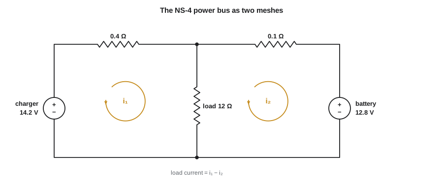
The charger behaves like a 14.2 V source with 0.4 Ω of internal resistance, the battery like a 12.8 V source with 0.1 Ω, and the load is 12 Ω. Using the meshes in the figure, find the mesh currents, the load current, the current into the battery and the power the charger delivers.
Show solution
- Mesh 1 (left): 0.4 i₁ + 12(i₁ − i₂) = 14.2, so 12.4 i₁ − 12 i₂ = 14.2.
- Mesh 2 (right), with the battery's + terminal at the top so that it opposes the clockwise current: 12(i₂ − i₁) + 0.1 i₂ = −12.8, so −12 i₁ + 12.1 i₂ = −12.8.
- \[\begin{bmatrix} 12.4 & -12 \\ -12 & 12.1 \end{bmatrix}\begin{bmatrix} i_1 \\ i_2 \end{bmatrix} = \begin{bmatrix} 14.2 \\ -12.8 \end{bmatrix}\]
- \[\Delta = 12.4(12.1) - 144 = 6.04\]
- \[i_1 = \frac{14.2(12.1) - 12(12.8)}{6.04} = \frac{18.22}{6.04} = 3.02\ \text{A}\]
- \[i_2 = \frac{12.4(-12.8) + 12(14.2)}{6.04} = \frac{11.68}{6.04} = 1.93\ \text{A}\]
- \[i_{load} = i_1 - i_2 = 1.08\ \text{A}, \qquad P_{charger} = 14.2(3.02) - 0.4(3.02)^2 = 39.2\ \text{W}\]
Answer: The charger supplies 3.02 A, of which 1.08 A feeds the load and 1.93 A flows into the battery, charging it, because i₂ is positive clockwise and so enters the battery's + terminal. The bus sits at 12 × 1.08 = 13.0 V. In reality the charger limits its own current, about 1.5 A on the NS-4, so this linear model overestimates it. Lesson 6 shows how to add that limit to the model.
The mesh method found the currents with two equations. Nodal analysis would also need only one unknown, the bus voltage, because the circuit has just two nodes. With practice, you will look at a circuit and choose the method that gives the fewest equations: count the meshes and the non-reference nodes, and remember that voltage sources reduce the node count while current sources reduce the mesh count.
Current sources and supermeshes
A current source in a branch belonging to only one mesh fixes that mesh's current, removing an unknown. A current source in a branch shared by two meshes causes the same difficulty that a floating voltage source causes in nodal analysis: its voltage is unknown and cannot be written with Ohm's law. The cure is the supermesh. Combine the two meshes into one larger loop that avoids the current source, write KVL around the combined loop, and add the constraint that the difference of the two mesh currents equals the source current.
Linearity and superposition
A linear circuit is made of linear elements, such as resistors, capacitors, inductors and linear dependent sources, together with independent sources. Two properties follow from the linearity of the equations. Homogeneity says that scaling every source by a factor scales every voltage and current by the same factor. Additivity says that the response to several sources acting together is the sum of the responses to each acting alone. Together they form the superposition principle.
To apply superposition, turn on one independent source at a time and turn the others off. A voltage source that is turned off is replaced by a short circuit, because its voltage becomes zero; a current source that is turned off is replaced by an open circuit, because its current becomes zero. Dependent sources are never turned off, because they are part of the circuit's behavior rather than inputs. Solve each single-source circuit, then add the results with their signs.
Worked problem
Superposition on the power bus
Find the load current in the previous example by superposition.
Show solution
- Charger alone (battery shorted): the 12 Ω load and the battery's 0.1 Ω are in parallel, giving 0.0992 Ω.
- \[i_{ch} = \frac{14.2}{0.4 + 0.0992} = 28.45\ \text{A}, \qquad i_{load,1} = 28.45 \times \frac{0.1}{12.1} = 0.235\ \text{A}\]
- Battery alone (charger shorted): the load and the charger's 0.4 Ω are in parallel, giving 0.387 Ω.
- \[i_{bat} = \frac{12.8}{0.1 + 0.387} = 26.28\ \text{A}, \qquad i_{load,2} = 26.28 \times \frac{0.4}{12.4} = 0.848\ \text{A}\]
- \[i_{load} = 0.235 + 0.848 = 1.08\ \text{A}\]
Answer: The two contributions add to 1.08 A, matching the mesh result. Superposition also shows that most of the load current, 0.85 A, comes from the battery's voltage and only 0.24 A from the extra voltage the charger provides. The large individual source currents in each step are not real; they exist only in the imaginary circuits with one source shorted.
Superposition applies to voltages and currents but not to power. Power is proportional to the square of current, and the square of a sum is not the sum of the squares. To find the power in an element, first add the currents or voltages from each source, then compute the power from the total.
Where superposition matters in digital hardware
Superposition is how engineers reason about signals that ride on top of each other. A logic signal traveling down a trace picks up a little crosstalk from its neighbor; the voltage at the receiver is the intended signal plus the crosstalk, each calculated separately. An analog sensor reading is the sensor's true voltage plus an offset from the amplifier plus noise from the switching regulator; the error budget adds the contributions. A 3.3 V rail carries its DC value plus ripple from the regulator plus spikes from chips switching. Treating each disturbance as a separate source and adding the effects is the core of signal-integrity and power-integrity analysis.
# Mesh analysis of the power bus, and a superposition check
def solve2(a, b, c, d, e, f):
    """Solve [[a, b], [c, d]] x = [e, f] by Cramer's rule."""
    det = a * d - b * c
    return (e * d - b * f) / det, (a * f - e * c) / det

Vch, Rch = 14.2, 0.4      # charger
Vb, Rb = 12.8, 0.1        # battery
RL = 12.0                 # load

i1, i2 = solve2(Rch + RL, -RL, -RL, RL + Rb, Vch, -Vb)
print("mesh currents: i1 = %.3f A, i2 = %.3f A" % (i1, i2))
print("load %.3f A, into battery %.3f A, bus %.2f V" % (i1 - i2, i2, RL * (i1 - i2)))

def par(a, b):
    return a * b / (a + b)

# superposition: one source at a time, the other shorted
i_load_1 = Vch / (Rch + par(RL, Rb)) * Rb / (Rb + RL)
i_load_2 = Vb / (Rb + par(RL, Rch)) * Rch / (Rch + RL)
print("charger alone %.3f A + battery alone %.3f A = %.3f A" % (i_load_1, i_load_2, i_load_1 + i_load_2))

# power does NOT superpose
p_true = (i1 - i2) ** 2 * RL
p_wrong = i_load_1 ** 2 * RL + i_load_2 ** 2 * RL
print("load power %.2f W; adding the separate powers would give %.2f W" % (p_true, p_wrong))mesh currents: i1 = 3.017 A, i2 = 1.934 A load 1.083 A, into battery 1.934 A, bus 12.99 V charger alone 0.235 A + battery alone 0.848 A = 1.083 A load power 14.07 W; adding the separate powers would give 9.29 W
Choosing a method
For hand analysis, count before you start. A circuit with five nodes and three meshes needs four nodal equations or three mesh equations. Subtract one equation for each voltage source tied to the reference node in nodal analysis, and one for each current source in an outer branch in mesh analysis. If the circuit is a ladder of series and parallel parts, reduction may be quickest of all. If the question asks about the effect of one particular source, superposition may answer it directly. Whatever method you choose, a second method or a power balance is the best check.
Common mistakes
MistakeTurning off a voltage source by removing it.
InsteadA source turned off for superposition becomes a short circuit if it is a voltage source and an open circuit if it is a current source.
MistakeTurning off dependent sources during superposition.
InsteadOnly independent sources are turned off; dependent sources stay in the circuit.
MistakeAdding powers from each source.
InsteadAdd currents or voltages first, then calculate power from the total.
MistakeUsing the wrong sign for a shared branch.
InsteadThe current in a shared branch is the difference of the two mesh currents, with the sign set by the direction of the mesh you are writing.
MistakeApplying mesh analysis to a non-planar circuit.
InsteadUse nodal analysis for circuits that cannot be drawn without crossings.
Summary and key terms
- Mesh analysis uses loop currents as unknowns and writes KVL around each mesh of a planar circuit.
- For resistors and voltage sources the equations form R i = v with a symmetric matrix that can be written by inspection.
- Current sources in shared branches are handled with supermeshes.
- Superposition: in a linear circuit the response to several sources is the sum of the responses to each alone, with other independent sources turned off.
- Superposition does not apply to power, and it underlies the analysis of noise, crosstalk and ripple.
- Mesh
- A loop in a planar circuit that contains no other loop.
- Mesh current
- A current assumed to circulate around a mesh; branch currents are sums or differences of mesh currents.
- Supermesh
- A combined loop around two meshes that share a current source.
- Planar circuit
- A circuit that can be drawn without crossing wires.
- Superposition
- The principle that a linear circuit's response to several sources is the sum of its responses to each alone.
- Homogeneity
- The property that scaling all sources scales every response by the same factor.
Practice problems
Work each problem on paper first, then reveal the answer to check.
A planar circuit has 7 branches and 4 nodes. How many meshes does it have?
Show answer
7 − 4 + 1 = 4.
When turned off for superposition, what replaces a voltage source? A current source?
Show answer
A short circuit; an open circuit.
Two sources each produce 2 mA in a 1 kΩ resistor, in the same direction. What is the power, and what would adding the separate powers give?
Show answer
Total 4 mA, so 16 mW; adding 4 mW + 4 mW would wrongly give 8 mW.
If every source in a linear circuit is doubled, what happens to the power in a resistor?
Show answer
Currents double, so power quadruples.
Give a reason to prefer nodal analysis over mesh analysis.
Show answer
It works on non-planar circuits, and voltage sources tied to ground reduce the number of unknowns.
Lesson quiz · 5 questions
Score 60% or more to complete this lesson.
Create a free account to save your progress, take quizzes and earn a certificate.