
CMP-240 · Lesson 3 of 12 · 22 min
Series, parallel and divider circuits in digital hardware
Most of the resistors on a microcontroller board belong to a handful of standard circuits: voltage dividers that scale a signal, pull-up and pull-down resistors that give an input a defined state, series resistors that limit current, and current-sharing paths. Each is a series or parallel combination, and each can be designed with nothing more than Ohm's law and Kirchhoff's laws. This lesson develops the combination rules properly and then works through the circuits that appear on every digital board, using the NS-4's service button, its I²C sensor bus and its 5 V radar interface as examples.
Resistors in series
Resistors are in series when the same current must flow through each, because they share nodes that nothing else connects to. KVL says the total voltage across the chain is the sum of the individual drops, and Ohm's law gives each drop as iR. The chain therefore behaves like one resistor whose value is the sum of the parts. Series resistance is always larger than the largest individual resistor.
The voltage divider follows directly. In a series chain the current is the total voltage divided by the total resistance, so the voltage across any one resistor is the total voltage multiplied by that resistor's share of the total. This voltage divider rule is used so often that it is worth memorizing: a resistor's voltage is its fraction of the series resistance times the applied voltage.
A divider gives the right voltage only when nothing draws significant current from its output. Any load connected across R2 is in parallel with it, which lowers the effective lower resistance and the output voltage, as the leakage example in lesson 2 showed. A good rule of thumb is that the current drawn by the load should be less than about one percent of the current through the divider. Lesson 6 replaces the rule of thumb with an exact method.
Resistors in parallel
Resistors are in parallel when they connect between the same two nodes and therefore share the same voltage. KCL says the total current is the sum of the branch currents, and each branch current is v/R. The combination behaves like a single resistor whose conductance is the sum of the conductances. Parallel resistance is always smaller than the smallest individual resistor.
For two resistors the formula simplifies to the product over the sum, written with the parallel operator R1 ∥ R2. Two equal resistors in parallel give half the value, and a resistor in parallel with one ten times larger is reduced by about 9 percent. These shortcuts let you estimate quickly whether a parallel path matters.
The current divider is the parallel counterpart of the voltage divider. In two parallel branches the current splits in inverse proportion to resistance: the smaller resistance takes the larger share. Expressed with conductances the rule has the same form as the voltage divider, each branch taking its share of the total conductance.
Simplifying networks
Ladder networks and other combinations can be reduced step by step: find a pair of elements that are clearly in series or in parallel, replace them with their equivalent, redraw, and repeat. The key is to check the definitions rather than the appearance of the drawing. Two resistors drawn side by side are in parallel only if both ends connect to the same two nodes; two resistors drawn in a line are in series only if no other branch joins the node between them. Some networks, such as a bridge, cannot be reduced this way at all and need the systematic methods of lessons 4 and 5.
Pull-up and pull-down resistors
A digital input pin has a very high input resistance and draws almost no current. If it is connected to nothing, its voltage floats: it drifts with static charge, picks up noise from nearby traces and may sit between the logic thresholds, where the input buffer wastes current and reads randomly. A pull-up resistor connects the input to the supply rail so that it reads 1 when nothing else drives it. A pull-down resistor connects it to ground so that it reads 0. A switch or an open-drain output then pulls the line the other way when activated.
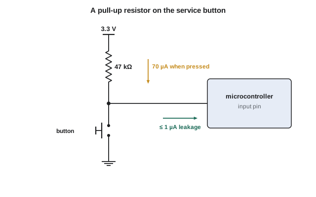
The NS-4's service button connects the microcontroller pin to ground when pressed, with a 47 kΩ pull-up to 3.3 V. With the button open, the only current is the pin's leakage, at most 1 µA by the datasheet, so the pin sits at 3.3 − (1 µA × 47 kΩ) = 3.25 V, well above the input-high threshold. With the button pressed, the pin is at ground and the resistor draws 3.3 V / 47 kΩ = 70 µA, but only while a technician is holding the button. Choosing the pull-up value is a trade between that pressed current and the noise immunity of the released state: a smaller resistor holds the line more firmly against interference, and a larger one wastes less power.
Worked problem
Choosing a pull-up for the service button
The microcontroller's input reads high above 0.7 × V_DD = 2.31 V and leaks up to 1 µA. Ines wants at least 0.5 V of margin above the threshold with the button released, and no more than 100 µA through the resistor when pressed. Find the allowed range of pull-up resistance and choose an E24 value.
Show solution
- Released, the pin voltage is 3.3 − I_leak R, which must be at least 2.31 + 0.5 = 2.81 V.
- \[R \le \frac{3.3 - 2.81}{1\ \mu\text{A}} = 490\ \text{k}\Omega\]
- Pressed, the current 3.3/R must be at most 100 µA.
- \[R \ge \frac{3.3}{100\ \mu\text{A}} = 33\ \text{k}\Omega\]
- Any value from 33 kΩ to 490 kΩ works; a value near the low end gives the best noise immunity.
Answer: The allowed range is 33 kΩ to 490 kΩ. The existing 47 kΩ part sits near the stiff end of that range, giving good immunity to the electrical noise from the radar while costing only 70 µA during a button press.
Open-drain outputs and the I²C bus
Many digital buses use open-drain (or open-collector) outputs, which can pull a line low but cannot drive it high. A single pull-up resistor per line restores the high level. Any device on the bus can pull the line low, and the line is high only when every device releases it, an arrangement called wired-AND. The NS-4's temperature and humidity sensor and its real-time clock share a two-wire I²C bus, with pull-up resistors on the clock line (SCL) and the data line (SDA).
The pull-up value on an I²C bus is bounded on both sides. It cannot be too small, because when a device pulls the line low it must sink the pull-up current while keeping the line below the low threshold; the I²C specification limits that sink current to 3 mA in standard and fast mode with the low level at most 0.4 V. It cannot be too large, because the pull-up must charge the bus capacitance quickly enough to meet the required rise time, a constraint that lesson 9 calculates. For now the lower bound follows from Ohm's law.
Two NS-4 boards from an early build had I²C errors that appeared only in cold weather. The cause was two modules on the bus each fitted with their own 2.2 kΩ pull-ups, in parallel with the main board's 2.2 kΩ pull-ups. Three 2.2 kΩ resistors in parallel make 733 Ω, below the 967 Ω minimum, so the weakest device could not pull the line low enough, and its output transistor weakened further as the temperature dropped. Removing the extra pull-ups from the modules fixed it. Parallel combinations hide in places like this, spread across boards and connectors.
Dividers for level shifting
The NS-4's radar module was designed for 5 V systems, and its serial transmit line swings from 0 to 5 V. Feeding 5 V into a 3.3 V microcontroller input would exceed its absolute maximum rating and could damage it. A simple voltage divider scales the 5 V signal down: with R1 = 10 kΩ from the radar output to the pin and R2 = 20 kΩ from the pin to ground, the pin sees 5 × 20/30 = 3.33 V when the radar output is high. Lesson 9 shows that the divider also slows the signal's edges, which limits how fast the serial link can run.
Worked problem
Worst-case divider output with tolerances
The radar's output high level is between 4.6 V and 5.25 V. The divider uses R1 = 10 kΩ and R2 = 20 kΩ, both 5 percent tolerance. The pin must see at least 2.31 V for a valid high and must never exceed 3.6 V. Check the worst cases.
Show solution
- Lowest output: smallest high level and smallest ratio, with R1 high and R2 low.
- \[v_{min} = 4.6 \times \frac{19}{10.5 + 19} = 4.6 \times 0.644 = 2.96\ \text{V} \ \ge 2.31\ \text{V}\]
- Highest output: largest high level and largest ratio, with R1 low and R2 high.
- \[v_{max} = 5.25 \times \frac{21}{9.5 + 21} = 5.25 \times 0.689 = 3.61\ \text{V}\]
Answer: The minimum of 2.96 V is safely a valid high, but the maximum of 3.61 V just exceeds the 3.6 V limit. Switching to 1 percent resistors gives a maximum of 5.25 × 20.2/(9.9 + 20.2) = 3.52 V, which passes. Worst-case analysis with tolerances, not nominal values, is what tells you whether a design is safe.
# Worst-case analysis of the radar level-shifting divider
from itertools import product

def divider(vin, r1, r2):
    return vin * r2 / (r1 + r2)

def worst_case(tol):
    R1, R2 = 10e3, 20e3
    results = []
    for vin, s1, s2 in product([4.6, 5.25], [-1, 1], [-1, 1]):
        r1 = R1 * (1 + s1 * tol)
        r2 = R2 * (1 + s2 * tol)
        results.append(divider(vin, r1, r2))
    return min(results), max(results)

for tol in (0.05, 0.01):
    lo, hi = worst_case(tol)
    ok = (lo >= 2.31) and (hi <= 3.6)
    print("tolerance %2.0f%%: pin from %.3f V to %.3f V -> %s" % (tol * 100, lo, hi, "pass" if ok else "fail"))

# Parallel pull-ups on the I2C bus
def par(*rs):
    return 1 / sum(1 / r for r in rs)
for n in (1, 2, 3):
    rp = par(*([2.2e3] * n))
print("%d x 2.2k in parallel = %4.0f ohm, sink current %.2f mA" % (n, rp, (3.3 - 0.4) / rp * 1e3))tolerance 5%: pin from 2.963 V to 3.615 V -> fail tolerance 1%: pin from 3.046 V to 3.523 V -> pass 1 x 2.2k in parallel = 2200 ohm, sink current 1.32 mA 2 x 2.2k in parallel = 1100 ohm, sink current 2.64 mA 3 x 2.2k in parallel = 733 ohm, sink current 3.95 mA
Current-sense resistors
Not every resistor exists to set a voltage. The NS-4's solar charger measures its output current with a 50 mΩ resistor in series with the battery lead; at 1.5 A it drops 75 mV, which an amplifier scales up for the microcontroller's ADC. A small resistance keeps the wasted power low, here 1.5² × 0.05 = 0.11 W, but means the measured voltage is small and the resistor's tolerance and the trace resistance of its connections matter. Designers connect the amplifier to the resistor's pads with separate traces, a Kelvin connection, so that the voltage dropped in the high-current traces is not added to the reading.
Common mistakes
MistakeAssuming two resistors are in parallel because they are drawn next to each other.
InsteadCheck that both ends connect to the same two nodes.
MistakeUsing the divider formula when the output is loaded.
InsteadInclude the load in parallel with the lower resistor, or confirm that the load current is negligible.
MistakeLeaving a digital input floating.
InsteadGive every input a defined state with a pull-up, pull-down or active driver.
MistakeAdding pull-up resistors on every module of a shared bus.
InsteadRemember that the pull-ups combine in parallel; keep the total within the bus specification.
MistakeDesigning with nominal values only.
InsteadCheck the worst cases with resistor tolerances and the full range of input voltages.
Summary and key terms
- Series resistances add, and the voltage divider gives each resistor its share of the total voltage.
- Parallel conductances add, the parallel resistance is below the smallest branch, and current divides in inverse proportion to resistance.
- Pull-up and pull-down resistors define the state of inputs that would otherwise float.
- Open-drain buses such as I²C need pull-ups whose value is bounded by the sink current and by the rise time.
- Dividers can shift logic levels, but only worst-case analysis with tolerances shows whether they are safe.
- Voltage divider
- A series chain whose output is a fraction of the input voltage set by the resistor ratio.
- Current divider
- Parallel branches that share a current in inverse proportion to their resistances.
- Pull-up resistor
- A resistor from a signal to the supply rail that holds it high when nothing drives it low.
- Open-drain output
- An output that can pull a line low but relies on a pull-up for the high level.
- Wired-AND
- A shared line that is high only when every connected open-drain device releases it.
- Kelvin connection
- Separate sense connections to a resistor so that voltage drops in the current-carrying traces are not measured.
- Worst-case analysis
- Checking a design at the combination of tolerances and inputs that gives the most extreme result.
Practice problems
Work each problem on paper first, then reveal the answer to check.
Find the equivalent of 1 kΩ in series with the parallel combination of 2 kΩ and 2 kΩ.
Show answer
2 kΩ ∥ 2 kΩ = 1 kΩ, plus 1 kΩ gives 2 kΩ.
Design a divider that gives 1.0 V from 3.3 V with about 100 µA total current.
Show answer
Total 33 kΩ; R2 = 10 kΩ and R1 = 23 kΩ (use 24 kΩ from E24, giving 0.97 V).
A 10 mA current splits between 100 Ω and 400 Ω. How much flows in each?
Show answer
8 mA in 100 Ω and 2 mA in 400 Ω.
Why does a floating CMOS input sometimes increase supply current?
Show answer
Its voltage can sit between thresholds, turning both transistors of the input stage partly on.
Two 4.7 kΩ pull-ups end up in parallel on one line. What is the effective pull-up and the sink current at 0.4 V from 3.3 V?
Show answer
2.35 kΩ; (3.3 − 0.4)/2350 ≈ 1.23 mA.
Lesson quiz · 5 questions
Score 60% or more to complete this lesson.
Create a free account to save your progress, take quizzes and earn a certificate.