
CIV-380 · Lesson 2 of 12 · 21 min
Reactors, hydraulics and tracer tests
Every tank in a treatment plant is a reactor. Coagulant reacts with particles in the rapid mix, chlorine inactivates pathogens in the clearwell, bacteria consume organic matter in the aeration tank and sludge decomposes in the digester. How well each reaction proceeds depends not only on its chemistry or biology but on how long each parcel of water spends in the tank, and that depends on the tank's hydraulics. This lesson builds on the reactor models of CIV-280 and applies them to the design of the new water plant's clearwell, where a tracer test on a similar tank at the city's existing plant has raised a concern.
Ideal reactors
Three ideal reactors frame the analysis. A batch reactor has no flow in or out; its contents react for a set time and are then emptied, as in a laboratory jar test or a sequencing batch reactor. A completely mixed flow reactor (CMFR, or continuously stirred tank reactor) is so well mixed that the concentration everywhere inside equals the outlet concentration. A plug flow reactor (PFR) moves water through as a series of parcels that do not mix with one another, like flow through a long, narrow pipe, so every parcel spends exactly the hydraulic residence time \(\tau = V/Q\) inside.
For a first-order reaction with rate constant \(k\), such as the decay of a disinfectant or the die-off of bacteria, steady-state mass balances give the outlet concentration of each reactor:
For the same volume and flow, the plug flow reactor always achieves more conversion of a first-order reaction than the completely mixed reactor, because in a CMFR the whole tank operates at the low outlet concentration. A series of CMFRs falls between the two and approaches plug flow as \(N\) grows. This is why disinfection contact tanks are built long and narrow, or divided by baffles into many compartments, while rapid-mix tanks, whose job is to spread a chemical instantly through the water, are built as small, intensely mixed CMFRs.
Worked problem
CMFR, plug flow and tanks in series
Chlorine contact is modeled as first-order inactivation of a pathogen with \(k = 0.10\) per minute. The tank has a residence time of 60 minutes. Find the surviving fraction if the tank behaves as a CMFR, as a plug flow reactor, and as four equal CMFRs in series.
Show solution
- CMFR:
- \[\frac{C}{C_0} = \frac{1}{1 + 0.10(60)} = 0.143\ \ (0.85\ \text{log})\]
- Plug flow:
- \[\frac{C}{C_0} = e^{-6.0} = 0.0025\ \ (2.6\ \text{log})\]
- Four tanks in series:
- \[\frac{C}{C_0} = \frac{1}{(1 + 6.0/4)^4} = 0.026\ \ (1.6\ \text{log})\]
Answer: The same tank gives 0.85-log, 1.6-log or 2.6-log inactivation depending on its hydraulics. Baffling is worth more than a bigger tank.
Real reactors and residence time distributions
Real tanks are neither perfectly mixed nor perfect plug flow. Inlet jets shoot across the tank, corners hold slow eddies, wind and temperature differences set up density currents, and some water reaches the outlet much sooner than \(\tau\) while some lingers much longer. The residence time distribution (RTD) describes this spread. It is measured with a tracer test: a conservative substance such as fluoride, lithium or a salt is added at the inlet, either as a short pulse or as a sudden step increase in feed, and its concentration is recorded at the outlet.
For a step input, the outlet response \(F(t)\) rises from 0 to 1 as the tracer replaces the original water. It gives directly the fraction of water that has spent less than time \(t\) in the tank. For a pulse input, the outlet curve \(E(t)\), normalized so that its area is 1, is the derivative of \(F\). From either curve, three times summarize the hydraulics: \(T_{10}\), the time by which 10 % of the tracer has passed, \(T_{50}\), the median, and \(T_{90}\). The mean residence time \(\bar t\) equals the area above the F curve:
If the mean residence time is well below \(\tau\), part of the tank is dead space that the flow bypasses. If \(T_{10}\) is very small, some water short-circuits from inlet to outlet. A Morrill index near 1 indicates plug flow; values above 2 to 3 indicate substantial mixing or short-circuiting.
The baffling factor in disinfection
Disinfection credit depends on the contact time that nearly all the water receives, not the average. Regulators therefore use \(T_{10}\), the time that 90 % of the water exceeds, in the CT calculation of lesson 6. Where no tracer test exists, \(T_{10}\) is estimated as the theoretical residence time multiplied by a baffling factor that depends on the tank's geometry. The values below are widely used in both Canadian and US guidance.
| Baffling condition | Baffling factor T10/τ | Description |
|---|---|---|
| Unbaffled (mixed) | 0.1 | No baffles, agitated, very low length-to-width ratio |
| Poor | 0.3 | Single or multiple unbaffled inlets and outlets, no intra-basin baffles |
| Average | 0.5 | Baffled inlet or outlet with some intra-basin baffles |
| Superior | 0.7 | Perforated inlet baffle, serpentine or perforated intra-basin baffles, outlet weir |
| Perfect (plug flow) | 1.0 | Very high length-to-width ratio, such as a pipeline |
Serpentine baffles that turn the flow back and forth through long, narrow channels are the usual way to reach 0.6 to 0.7 in a clearwell. A length-to-width ratio of the flow path of 20 or more is a common target. Inlet design matters as much as the baffles: a pipe discharging straight at the outlet can ruin an otherwise good tank.
The existing clearwell test
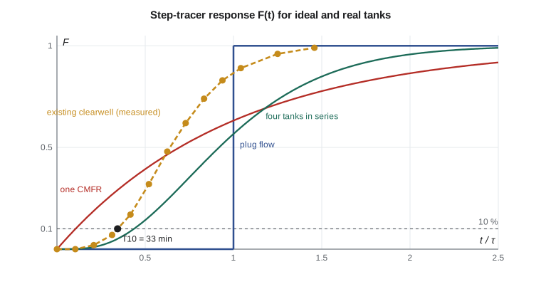
Before committing to a clearwell design, Martin asks Joy to run a step tracer test on the existing plant's clearwell, which holds about 1.06 million gallons and has the same rectangular plan as the proposed new tank. At a steady flow equal to the new plant's peak of 16 MGD, she switches the fluoride feed from off to on and samples the outlet every ten minutes. The script analyses her results.
# Step-tracer test on the new clearwell: T10, baffling factor and tanks in series
from math import exp, factorial
UNITS = "US"
SI = UNITS == "SI"
if SI:
    V, Q, uv, uq = 4000.0, 60000.0 / 1440, "m3", "m3/min"     # volume, peak flow per minute
else:
    V, Q, uv, uq = 1.06e6, 16.0e6 / 1440, "gal", "gal/min"
HRT = V / Q
# measured response to a step change in fluoride: fraction of the step at the outlet
t = [0, 10, 20, 30, 40, 50, 60, 70, 80, 90, 100, 120, 140]          # minutes
F = [0, 0.00, 0.02, 0.07, 0.17, 0.32, 0.48, 0.62, 0.74, 0.83, 0.89, 0.96, 0.99]
def t_at(f):                                    # linear interpolation for time at fraction f
    for i in range(1, len(F)):
        if F[i] >= f:
            return t[i-1] + (f - F[i-1]) * (t[i] - t[i-1]) / (F[i] - F[i-1])
T10 = t_at(0.10); T50 = t_at(0.50); T90 = t_at(0.90)
tbar = sum((1 - (F[i] + F[i-1]) / 2) * (t[i] - t[i-1]) for i in range(1, len(t)))   # mean residence time
print(f"theoretical HRT = {V:,.0f} {uv} / {Q:,.0f} {uq} = {HRT:.1f} min")
print(f"T10 = {T10:.1f} min, T50 = {T50:.1f} min, T90 = {T90:.1f} min, mean = {tbar:.1f} min")
print(f"baffling factor T10/HRT = {T10/HRT:.2f}, Morrill index T90/T10 = {T90/T10:.2f}")
# tanks-in-series model: find N whose T10/tau matches the measurement
def F_n(theta, n):                              # step response of n equal CMFRs, theta = t/tau
    x = n * theta
    return 1 - exp(-x) * sum(x**k / factorial(k) for k in range(n))
for n in (1, 2, 4, 8, 12, 20):
    lo, hi = 0.0, 3.0
    for _ in range(60):
        mid = (lo + hi) / 2
        lo, hi = (mid, hi) if F_n(mid, n) < 0.10 else (lo, mid)
print(f"N = {n:2d} tanks in series: T10/tau = {lo:.2f}")theoretical HRT = 1,060,000 gal / 11,111 gal/min = 95.4 min T10 = 33.0 min, T50 = 61.4 min, T90 = 102.9 min, mean = 65.0 min baffling factor T10/HRT = 0.35, Morrill index T90/T10 = 3.12 N = 1 tanks in series: T10/tau = 0.11 N = 2 tanks in series: T10/tau = 0.27 N = 4 tanks in series: T10/tau = 0.44 N = 8 tanks in series: T10/tau = 0.58 N = 12 tanks in series: T10/tau = 0.65 N = 20 tanks in series: T10/tau = 0.73
The results are disappointing. The theoretical residence time is about 96 minutes, but \(T_{10}\) is only 33 minutes, a baffling factor of 0.34, in the poor range. The mean residence time of 65 minutes is a third shorter than \(\tau\), which means about a third of the tank is effectively dead space. The equivalent number of tanks in series, matched on \(T_{10}/\tau\), is between two and four. The tank has a single inlet pipe in one corner and an outlet in the opposite corner, so the flow cuts diagonally across and leaves the other two corners stagnant.
Nadia's proposal for the new clearwell divides the same footprint with three longitudinal baffle walls into four passes, with a perforated inlet diffuser and an outlet weir across the full width. Published tests on similar layouts suggest a baffling factor of 0.6. The team adopts that value for the CT calculation in lesson 6 and specifies a tracer test at commissioning to confirm it; if the test falls short, the design allows an extra baffle wall to be added.
Worked problem
Dead space from a tracer test
A tank with a theoretical residence time of 96 minutes has a measured mean residence time of 65 minutes. Estimate the fraction of the tank that behaves as dead space.
Show solution
- If the active volume carries all the flow, its residence time equals the measured mean:
- \[\frac{V_{active}}{V} = \frac{\bar t}{\tau} = \frac{65}{96} = 0.68\]
- \[\text{dead fraction} = 1 - 0.68 = 0.32\]
Answer: About a third of the tank does no useful work.
Hydraulics of the whole plant
Water moves through most treatment plants by gravity, from the raw water pumping station to the clearwell, and through wastewater plants from the headworks to the outfall. The designer prepares a hydraulic profile that tracks the water surface elevation through each unit at peak flow, adding up the head losses through channels, weirs, gates, pipes, filters and clarifiers. Typical losses are 0.1 to 0.3 m through a weir, 0.3 to 0.6 m through a clean filter rising to 2 to 3 m at the end of a run, and smaller losses through each pipe and fitting, computed with the methods of CIV-270 and CIV-370. The profile sets the elevation of every tank and decides whether intermediate pumping is needed.
Flow must also be split evenly among parallel units. Unequal splitting overloads one basin while another is underused, and an overloaded basin performs worse than average, so the plant as a whole underperforms. Splitting is done with identical free-falling weirs, which make the flow to each unit depend only on the weir length, or with flow meters and control valves. Designers check that splitting stays acceptable at low flow, when weirs become sensitive to small differences in crest level.
Finally, the design must work with one unit out of service. Ten States Standards and most provincial guidelines require that the plant meet its design capacity with the largest unit of each process removed for maintenance, and that no single failure stop the plant. This redundancy rule drives the number of basins and filters as strongly as the hydraulics do.
Mixing in the rapid mix and flocculators
The rapid mix has the opposite goal from the clearwell: it must distribute a chemical through all the water within seconds, before the coagulant hydrolyzes and precipitates. It is designed as a small CMFR with a residence time of a few seconds to a minute, or as an in-line static or pumped-jet mixer. Flocculation, by contrast, needs a long, gentle residence with a narrow RTD, so flocculators are built as three or four compartments in series. Both are designed using the velocity gradient of lesson 3, which links mixing intensity to power input.
Common mistakes
MistakeUsing the theoretical residence time V/Q in the CT calculation.
InsteadUse T10 from a tracer test or a baffling factor.
MistakeAssuming a larger tank always improves disinfection.
InsteadPoor hydraulics waste volume; baffles and inlet design matter more.
MistakeSizing parallel units without checking the flow split.
InsteadUse identical weirs or controlled splitting and check at low flow.
Summary and key terms
- First-order conversion is greatest in plug flow, least in a single CMFR, and intermediate in tanks in series.
- Tracer tests measure the residence time distribution; \(T_{10}\), \(T_{50}\), \(T_{90}\) and \(\bar t\) summarize it.
- The baffling factor \(T_{10}/\tau\) ranges from 0.1 for unbaffled tanks to 1.0 for plug flow.
- Hydraulic profiles, even flow splitting and redundancy shape the layout of the whole plant.
- CMFR
- A completely mixed flow reactor in which the outlet concentration equals the tank concentration.
- Plug flow reactor
- A reactor in which parcels move through without mixing, each staying for the residence time.
- Residence time distribution
- The spread of times that water parcels spend in a reactor.
- T10
- The time by which 10 % of a tracer has passed the outlet.
- Baffling factor
- The ratio of T10 to the theoretical residence time.
- Morrill index
- The ratio T90/T10, a measure of dispersion.
- Hydraulic profile
- A plot of water surface elevations through a plant at design flow.
Practice problems
Work each problem on paper first, then reveal the answer to check.
A first-order reaction with \(k = 0.2\) per hour proceeds in a tank with \(\tau = 5\) h. Compare CMFR and plug flow conversion.
Show answer
CMFR: \(1/(1 + 1) = 0.50\) remaining; PFR: \(e^{-1} = 0.37\) remaining.
A clearwell with \(\tau = 80\) min has a baffling factor of 0.5. What is \(T_{10}\)?
Show answer
\(T_{10} = 0.5 \times 80 = 40\) min.
A tracer test gives \(T_{10} = 12\) min and \(T_{90} = 60\) min. Find the Morrill index and comment.
Show answer
\(60/12 = 5\); the tank is far from plug flow, with strong mixing or short-circuiting.
Why must a plant be able to meet design flow with one filter out of service?
Show answer
Filters are routinely backwashed and maintained; capacity must not depend on every unit being available.
Lesson quiz · 5 questions
Score 60% or more to complete this lesson.
Create a free account to save your progress, take quizzes and earn a certificate.