
CIV-331 · Lesson 8 of 12 · 17 min
Beam-columns and combined forces
Few members carry pure axial load or pure bending. A column in a moment frame bends as the frame resists wind; a wall column carries roof load and spans between floors to resist wind on the cladding; a truss top chord carries joist loads between panel points. These are beam-columns. Their design combines the column rules of lesson 4 and the beam rules of lessons 5 and 6 in interaction equations, and it must account for the extra moment that the axial load produces as the member deflects. This lesson develops the interaction checks and applies them to a wall column of the maintenance bay.
Second-order moments
Consider a pinned column with an axial load \(P\) and a uniform lateral load that bends it. The lateral load alone gives a first-order moment \(M_o\) and a deflection \(\delta_o\). With the axial load acting on the deflected shape, each section has an additional moment \(P\delta\), which increases the deflection, which increases the moment again. The process converges to an amplified moment:
This member effect, called \(P\)-\(\delta\), is significant only when \(P\) is a noticeable fraction of the Euler load of the member in the plane of bending. The factor \(C_m\) accounts for the shape of the first-order moment diagram. For a member bent in single curvature by end moments, or by a transverse load, the deflected shape adds to the existing moment where it is largest, and \(C_m\) is close to 1.0. For a member bent in reverse curvature by end moments, the maximum first-order moment is at an end, where the deflection is zero, and the amplification is smaller.
A second effect, \(P\)-\(\Delta\), arises when a whole story sways: the gravity loads acting on the displaced frame add overturning moment to every column. It belongs to the frame, not to one member, and lesson 11 treats it. A column in a braced frame, such as the wall column in this lesson, has only the \(P\)-\(\delta\) effect.
Interaction of axial load and bending
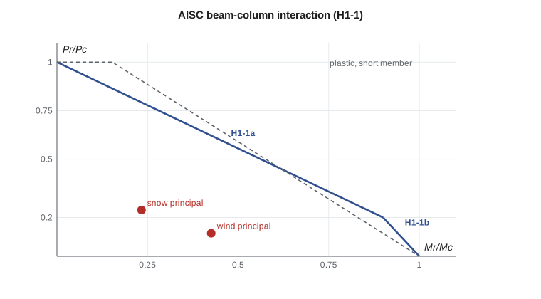
A short member that is fully yielded under axial load and moment together has an interaction curve between \(P/P_y = 1\) and \(M/M_p = 1\). For a W shape bent about its strong axis, that curve is nearly a straight line from \((0, 1)\) to about \((0.15, 1)\) and then down to \((1, 0)\): a small axial load barely reduces the plastic moment, because the web carries the axial force near the neutral axis. For longer members, buckling under axial load and lateral-torsional buckling under bending reduce both end points, and the second-order amplification bends the curve inward.
AISC 360 Section H1 uses a bilinear interaction:
Here \(P_r\) and \(M_r\) are the required axial and flexural strengths, including second-order effects, and \(P_c = \phi_cP_n\) and \(M_c = \phi_bM_n\) are the design strengths from Chapters E and F. \(P_c\) is the strength for the governing axis of buckling, and \(M_c\) includes lateral-torsional buckling and flange local buckling. The equations were fitted to the results of second-order inelastic analyses of real members, which is why they bend at \(P_r/P_c = 0.2\).
Second-order analysis and B1
AISC requires the required strengths \(P_r\) and \(M_r\) to include second-order effects. The direct analysis method of Chapter C obtains them from a second-order analysis with reduced stiffness and notional loads (lesson 11). Alternatively, Appendix 8 amplifies first-order moments: \(M_r = B_1M_{nt} + B_2M_{lt}\), where \(B_1 = C_m/(1 - \alpha P_r/P_{e1}) \ge 1\) covers \(P\)-\(\delta\) and \(B_2\) covers \(P\)-\(\Delta\). For a member in a braced frame, \(B_2\) does not apply. \(C_m = 0.6 - 0.4M_1/M_2\) for members with end moments only, with \(M_1/M_2\) positive for reverse curvature, and \(C_m = 1.0\) conservatively for transverse loading. With the direct analysis method, \(P_{e1}\) uses \(EI^* = 0.8\tau_bEI\).
The maintenance bay wall column
The end-wall columns of the maintenance bay are 20 ft high, pinned at the base and at the roof, and the roof and wall bracing prevent sway. Each column supports the end reaction of a roof truss, \(D = 15.6\) kips and \(S = 31.5\) kips, and spans vertically between base and roof to resist wind on the wall cladding, delivered by horizontal girts. The columns are 25 ft apart and the net strength-level wind pressure is 30 psf, so the wind load is 0.75 kip/ft and its moment is \(0.75(20)^2/8 = 37.5\) kip·ft. The girts at mid-height brace the column about its weak axis, but under wind suction the inner flange is in compression and is unbraced over the full 20 ft.
Two combinations compete. Combination 3, with snow principal and wind companion, gives the largest axial load: \(P_u = 1.2(15.6) + 1.6(31.5) = 69.1\) kips with \(M_u = 0.5(37.5) = 18.8\) kip·ft. Combination 4, with wind principal and snow companion, gives the largest moment: \(P_u = 34.5\) kips with \(M_u = 37.5\) kip·ft. Both are checked, together with 0.9D + 1.0W.
Worked problem
Wall column under snow and wind
Check a W8x31 (\(A = 9.13\) in², \(I_x = 110\) in⁴, \(S_x = 27.5\) in³, \(Z_x = 30.4\) in³, \(r_x = 3.47\) in., \(r_y = 2.02\) in., noncompact flange from lesson 2) for combination 4: \(P_u = 34.5\) kips, \(M_u = 37.5\) kip·ft.
Show solution
- Axial strength: about x, \(KL/r = 240/3.47 = 69.2\); about y with the girts, \(120/2.02 = 59.4\). The x axis governs: \(P_c = \phi_cP_n = 290\) kips.
- Flexural strength: flange local buckling gives \(M_n = 126.5\) kip·ft, just below \(M_p = 126.7\). For LTB, \(L_p = 7.14\) ft, \(L_r = 25.0\) ft, and with \(L_b = 20\) ft and \(C_b = 1.14\), \(M_n = 106.3\) kip·ft, so \(M_c = 0.90(106.3) = 95.6\) kip·ft.
- Amplification with \(C_m = 1.0\) and \(EI^* = 0.8EI\):
- \[P_{e1} = \frac{\pi^2(0.8)(29{,}000)(110)}{240^2} = 437\ \text{kips} \qquad B_1 = \frac{1.0}{1 - 34.5/437} = 1.09 \qquad M_r = 1.09(37.5) = 40.7\ \text{kip·ft}\]
- \(P_r/P_c = 34.5/290 = 0.12 < 0.2\), so Equation H1-1b applies:
- \[\frac{34.5}{2(290)} + \frac{40.7}{95.6} = 0.06 + 0.43 = 0.49 \le 1.0\]
Answer: The interaction value is 0.49 for combination 4; combination 3 gives 0.45 with H1-1a. The W8x31 is adequate.
The program checks all three load combinations, so that no combination is missed when loads change. It also computes the wind deflection.
import math
# Wall column W8x31 (noncompact flange): axial load from the truss plus wind, AISC 360 Chapter H
E, Fy = 29000.0, 50.0
A, Ix, Sx, Zx, rx, ry, rts, J, ho = 9.13, 110, 27.5, 30.4, 3.47, 2.02, 2.28, 0.536, 7.57
L, Ly, Lb = 240.0, 120.0, 20.0         # height (in.); weak axis braced by girts (in.); inner flange unbraced (ft)

D, S, Wm = 0.52 * 30, 1.05 * 30, 0.75 * 20**2 / 8     # truss reactions (kips) and wind moment (kip-ft)
combos = {"1.2D + 1.6S + 0.5W": (1.2 * D + 1.6 * S, 0.5 * Wm),
          "1.2D + 1.0W + 0.5S": (1.2 * D + 0.5 * S, 1.0 * Wm),
          "0.9D + 1.0W":        (0.9 * D, 1.0 * Wm)}

def phiPn(KL, r):
    Fe = math.pi**2 * E / (KL / r)**2
    Fcr = 0.658**(Fy / Fe) * Fy if Fy / Fe <= 2.25 else 0.877 * Fe
    return 0.90 * Fcr * A

Pc = min(phiPn(L, rx), phiPn(Ly, ry))
Mp = Fy * Zx / 12
lam, lp, lr = 9.19, 0.38 * math.sqrt(E / Fy), 1.0 * math.sqrt(E / Fy)
Mn_flb = Mp - (Mp - 0.7 * Fy * Sx / 12) * (lam - lp) / (lr - lp)
Lp = 1.76 * ry * math.sqrt(E / Fy) / 12
aj = J / (Sx * ho)
Lr = 1.95 * rts * E / (0.7 * Fy) * math.sqrt(aj + math.sqrt(aj**2 + 6.76 * (0.7 * Fy / E)**2)) / 12
Cb = 1.14
if Lb <= Lr:
    Mn_ltb = min(Cb * (Mp - (Mp - 0.7 * Fy * Sx / 12) * (Lb - Lp) / (Lr - Lp)), Mp)
else:
    x = Lb * 12 / rts
    Mn_ltb = min(Cb * math.pi**2 * E / x**2 * math.sqrt(1 + 0.078 * aj * x**2) * Sx / 12, Mp)
Mc = 0.90 * min(Mn_flb, Mn_ltb)
Pe1 = math.pi**2 * 0.8 * E * Ix / L**2           # EI* = 0.8EI for the direct analysis method
print(f"Pc = {Pc:.0f} kips; Mp = {Mp:.1f}, Mn(FLB) = {Mn_flb:.1f}, Lp = {Lp:.2f} ft, Lr = {Lr:.1f} ft, "
      f"Mn(LTB) = {Mn_ltb:.1f}, Mc = {Mc:.1f} kip-ft; Pe1 = {Pe1:.0f} kips")

for name, (Pr, Mr0) in combos.items():
    B1 = max(1.0 / (1 - Pr / Pe1), 1.0)           # Cm = 1.0 for the transverse wind load
    Mr = B1 * Mr0
    ratio = Pr / Pc + 8 / 9 * Mr / Mc if Pr / Pc >= 0.2 else Pr / (2 * Pc) + Mr / Mc
    eq = "H1-1a" if Pr / Pc >= 0.2 else "H1-1b"
    print(f"{name}: Pr = {Pr:4.1f} kips, Mr = {Mr:4.1f} kip-ft (B1 = {B1:.3f}), Pr/Pc = {Pr/Pc:.2f}, {eq} = {ratio:.2f}")

# Wind deflection with 0.42 x the strength-level wind (about a 10-year wind)
d = 5 * (0.42 * 0.75 / 12) * L**4 / (384 * E * Ix)
print(f"Wind deflection = {d:.2f} in. = L/{L/d:.0f}")Pc = 290 kips; Mp = 126.7, Mn(FLB) = 126.5, Lp = 7.14 ft, Lr = 25.0 ft, Mn(LTB) = 106.3, Mc = 95.6 kip-ft; Pe1 = 437 kips 1.2D + 1.6S + 0.5W: Pr = 69.1 kips, Mr = 22.3 kip-ft (B1 = 1.188), Pr/Pc = 0.24, H1-1a = 0.45 1.2D + 1.0W + 0.5S: Pr = 34.5 kips, Mr = 40.7 kip-ft (B1 = 1.086), Pr/Pc = 0.12, H1-1b = 0.49 0.9D + 1.0W: Pr = 14.0 kips, Mr = 38.7 kip-ft (B1 = 1.033), Pr/Pc = 0.05, H1-1b = 0.43 Wind deflection = 0.36 in. = L/675
The column is used at about half its capacity. A lighter W8 would satisfy strength, but the team kept the W8x31 because it is the same section that was considered for the mezzanine columns, simplifies purchasing and keeps the wind deflection small, about 0.36 in. or span/675 under a serviceability wind of 0.42 times the strength-level wind, which suits the metal cladding.
Other beam-column cases
- Truss chords with loads between panel points: purlins or joists that bear on the top chord between joints bend it locally. The chord is a beam-column, continuous over the panel points, with the local moment amplified by the chord's axial compression.
- Columns with eccentric beam reactions: a beam bearing on a column cap or a seat at some distance from the column axis applies a moment equal to the reaction times the eccentricity. In simple construction a nominal eccentricity, typically the distance to the face of the column plus 100 mm (4 in.), is taken and split between the column lengths above and below.
- Moment frame columns: the moments come from the frame analysis and include sway effects. Lesson 11 shows how the amplification changes.
- Biaxial bending: corner columns and columns with eccentric loads in both directions add a weak-axis term. The weak-axis moment resistance of a W shape is about 1.5 times \(S_y F_y\) and the weak-axis term often adds noticeably to the interaction.
Tension with bending
Members in tension and bending, such as a truss bottom chord carrying a hoist load between panel points, are checked with the same H1 equations using the tensile strength in place of \(P_c\). AISC permits \(C_b\) to be increased by \(\sqrt{1 + \alpha P_r/P_{ey}}\) because tension reduces lateral-torsional buckling. Tension straightens the member, so no amplification is needed.
Common mistakes
MistakeChecking only the load case with the largest axial load.
InsteadCheck every combination; the largest moment case often governs a wall column.
MistakeUsing \(C_m = 0.6 - 0.4M_1/M_2\) for a member with transverse load.
Instead\(C_m = 1.0\) conservatively for transversely loaded members.
MistakeUsing \(M_p\) for a section with a noncompact flange.
Instead\(M_c\) must include flange local buckling and LTB.
MistakeForgetting that the girts brace only one flange.
InsteadUnder suction the unbraced inner flange is in compression; use the full height for LTB.
Summary and key terms
- Beam-columns combine axial load and bending; the axial load amplifies moments through the \(P\)-\(\delta\) effect.
- AISC: \(P_r/P_c + (8/9)M_r/M_c \le 1.0\) for \(P_r/P_c \ge 0.2\), else \(P_r/2P_c + M_r/M_c \le 1.0\).
- \(B_1 = C_m/(1 - \alpha P_r/P_{e1}) \ge 1\) amplifies non-sway moments; \(B_2\) covers sway.
- Check all load combinations; for wall columns the wind-principal case often governs.
- The W8x31 wall column has a governing interaction value of 0.49 (combination 4).
- Beam-column
- A member that carries axial load and bending together.
- P-delta effect
- Additional moment from axial load acting on the deflection of a member between its ends (P-δ).
- P-Delta effect
- Additional moment from gravity loads acting on the sway of a story (P-Δ).
- Amplification factor B1
- B1 = Cm/(1 − αPr/Pe1), the factor that magnifies non-sway moments.
- Equivalent moment factor Cm
- The factor that accounts for the shape of the first-order moment diagram in amplification.
- Single curvature
- Bending of a member so that it is concave on one side along its full length.
- Interaction equation
- An expression that combines the ratios of load effects to resistances for several actions.
- Girt
- A horizontal member that supports wall cladding and spans between columns.
Practice problems
Work each problem on paper first, then reveal the answer to check.
A braced column has end moments of 40 and −20 kip·ft bending it in reverse curvature. Find \(C_m\).
Show answer
\(M_1/M_2 = +0.5\) for reverse curvature, so \(C_m = 0.6 - 0.4(0.5) = 0.4\).
For combination 3 of the wall column, show that H1-1a gives about 0.45.
Show answer
\(B_1 = 1/(1 - 69.1/437) = 1.19\); \(M_r = 22.3\); \(69.1/290 + (8/9)(22.3/95.6) = 0.24 + 0.21 = 0.45\).
Why does a small axial load barely reduce the plastic moment of a W shape?
Show answer
The axial force can be carried by a strip of web near the neutral axis, which contributes little to the moment.
Why is no amplification applied to a member in tension and bending?
Show answer
Tension reduces the deflection rather than increasing it.
Lesson quiz · 5 questions
Score 60% or more to complete this lesson.
Create a free account to save your progress, take quizzes and earn a certificate.