
CIV-331 · Lesson 6 of 12 · 18 min
Lateral-torsional buckling of beams
A deep, narrow beam bent about its strong axis is like a column lying on its side: its compression flange wants to buckle, and the easiest way is sideways. Because the tension flange resists moving sideways, the section twists as it deflects laterally. This combined sideways bending and twisting is lateral-torsional buckling (LTB). It governs beams whose compression flange is not braced, such as girders between their connected beams, beams during erection before the deck is fixed, crane runways and monorails. This lesson explains the behavior, gives the design rules, and checks the mezzanine edge girder.
How a beam buckles laterally
Picture a long scale ruler loaded on edge between two supports that stop it twisting at the ends. Under a small load it bends downward in its stiff plane. At a critical load it suddenly kicks sideways and twists, and it can carry little more. The critical moment depends on two kinds of resistance: the lateral bending stiffness of the section, \(EI_y\), and its torsional stiffness. Torsional stiffness itself has two parts. St. Venant torsion, \(GJ\), is the resistance of the plates to shear as they twist. Warping torsion, \(EC_w\), is the resistance of the flanges to bending in opposite directions in their own planes as an I-section twists.
For a doubly symmetric beam with simple end supports that prevent twist but allow warping, under uniform moment, the elastic critical moment is
where \(L\) is the unbraced length \(L_b\). AISC writes the same result as a critical stress \(F_{cr}\) on \(S_x\) in terms of \(r_{ts}\), a radius of gyration of the compression flange plus part of the web, and \(h_o\), the distance between flange centroids. The first term under the root dominates for long beams and for compact sections such as HSS; the warping term dominates for short, deep I-beams.
Torsional stiffness falls quickly with length, so the critical moment falls even faster than a column's buckling load: halving the unbraced length can more than double the critical moment.
Real beams: three regions
Like columns, real beams have initial crookedness and residual stresses. The design curves therefore have three regions:
- Short unbraced lengths: the beam reaches \(M_p\) (for compact or class 1 and 2 sections) before buckling.
- Intermediate lengths: part of the section yields before the beam buckles, and the strength falls between \(M_p\) and a value near \(0.7M_y\).
- Long lengths: the beam buckles elastically at the critical moment.
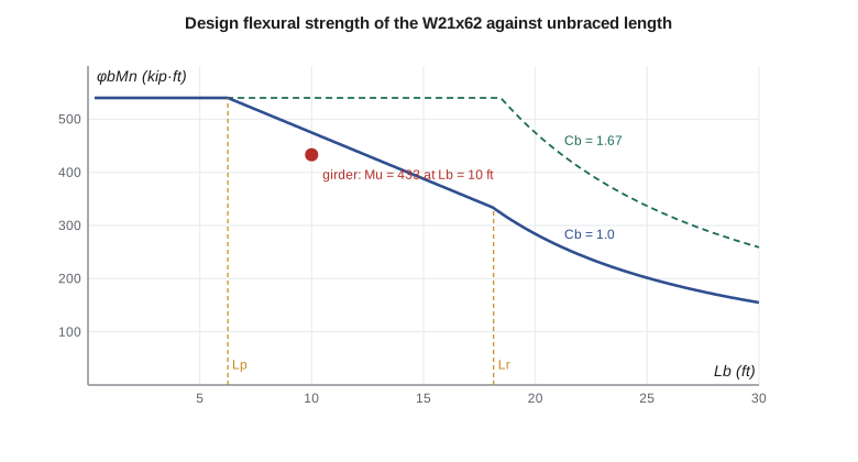
AISC 360 Section F2 defines two limiting lengths, \(L_p\) and \(L_r\), with a straight line between them:
Beyond \(L_r\), \(F_{cr} = \dfrac{C_b\pi^2E}{(L_b/r_{ts})^2}\sqrt{1 + 0.078\dfrac{Jc}{S_xh_o}\Big(\dfrac{L_b}{r_{ts}}\Big)^2}\) and \(M_n = F_{cr}S_x \le M_p\). \(L_r\) is the length at which this elastic expression gives \(0.7F_yS_x\). For doubly symmetric I-shapes \(c = 1.0\).
Moment gradient: the factor Cb
The expressions above assume a uniform moment over the unbraced length, which is the worst case: the whole compression flange is equally stressed. When the moment varies along the segment, only part of the flange is highly stressed and the beam is stronger. The equivalent moment factor accounts for this, using the maximum moment and the moments at the quarter points of the unbraced segment:
It is 1.0 for uniform moment, 1.14 for a simply supported span under uniform load, 1.32 for a central point load, and 1.67 for a moment varying linearly from zero to a maximum. It multiplies the strength in the inelastic and elastic regions but never above \(M_p\).
Bracing and load height
A brace for lateral-torsional buckling must prevent either lateral movement of the compression flange or twist of the section. Beams framing in at mid-depth with simple connections, cross frames, and a deck fastened to the compression flange all do this. A tension flange brace does little. Braces need both strength and stiffness; lesson 11 gives the requirements.
The expressions assume the load is applied at the shear center. Load on the top flange, free to move with the beam, tips the section further as it twists and lowers the critical moment. AISC's commentary recommends taking \(C_b = 1.0\) or using a reduced value for such loads, and treats cantilevers separately. Load hanging from the bottom flange, as from a monorail trolley, is stabilizing.
The mezzanine edge girder
The edge girders span 30 ft between columns and receive the mezzanine beams at their third points. The beams frame in with double-angle connections at mid-depth and brace the girder there, so the girder has three unbraced segments of 10 ft. The deck spans parallel to the girder and does not brace it. The required moment, including self-weight, is \(M_u = 425 + 1.2(0.062)(30)^2/8 = 433\) kip·ft, nearly uniform over the middle segment.
Worked problem
Edge girder with braces at the third points
Check a W21x62 (\(Z_x = 144\) in³, \(S_x = 127\) in³, \(r_y = 1.77\) in., \(r_{ts} = 2.15\) in., \(J = 1.83\) in⁴, \(h_o = 20.4\) in., compact) for \(M_u = 433\) kip·ft over the middle segment, \(L_b = 10\) ft, \(C_b = 1.0\).
Show solution
- \[M_p = \frac{50(144)}{12} = 600\ \text{kip·ft} \qquad \phi_b M_p = 540\ \text{kip·ft}\]
- Limiting lengths:
- \[L_p = 1.76(1.77)\sqrt{\frac{29{,}000}{50}}\,\frac{1}{12} = 6.25\ \text{ft} \qquad L_r = 18.1\ \text{ft (from the expression, as in the Manual)}\]
- \(L_p < L_b = 10 < L_r\), so the inelastic expression applies:
- \[M_n = 1.0\Big[600 - \Big(600 - \frac{0.7(50)(127)}{12}\Big)\frac{10 - 6.25}{18.1 - 6.25}\Big] = 600 - 229.6(0.316) = 527\ \text{kip·ft}\]
- \[\phi_b M_n = 0.90(527) = 475\ \text{kip·ft} \ge 433\]
Answer: \(\phi_b M_n = 475\) kip·ft against \(M_u = 433\) kip·ft, a ratio of 0.91. The end segments, with \(C_b = 1.67\), reach \(\phi_b M_p = 540\) kip·ft and are not critical. The W21x62 works, but only because the beams brace it at the third points.
If the same girder had no braces between columns, its strength over 30 ft with \(C_b = 1.14\) would fall to about 177 kip·ft, well under half of what it needs. Bracing, not the size of the beam, is what makes it work.
Sofia's program computes the resistance of each segment, tabulates the resistance against unbraced length, which is how the curve in the figure was drawn, and checks the girder during erection, when it is in place but the beams are not yet connected.
import math
# Mezzanine edge girder W21x62: lateral-torsional buckling, AISC 360 Section F2
E, Fy, phi = 29000.0, 50.0, 0.90
Zx, Sx, ry, rts, J, ho = 144.0, 127.0, 1.77, 2.15, 1.83, 20.4
Mp = Fy * Zx / 12
P, L = 42.5, 30.0                                  # beam reactions (kips) at third points
Mu = P * L / 3 + 1.2 * 0.062 * L**2 / 8
Lp = 1.76 * ry * math.sqrt(E / Fy) / 12
c = 1.0
a = J * c / (Sx * ho)
Lr = 1.95 * rts * E / (0.7 * Fy) * math.sqrt(a + math.sqrt(a**2 + 6.76 * (0.7 * Fy / E)**2)) / 12
print(f"Mu = {Mu:.1f} kip-ft, Mp = {Mp:.0f} kip-ft, phiMp = {phi*Mp:.0f} kip-ft, Lp = {Lp:.2f} ft, Lr = {Lr:.1f} ft")

def Cb(Mmax, Ma, Mb, Mc):
    return 12.5 * Mmax / (2.5 * Mmax + 3 * Ma + 4 * Mb + 3 * Mc)

def phiMn(Lb, cb):
    if Lb <= Lp:
        Mn = Mp
    elif Lb <= Lr:
        Mn = min(cb * (Mp - (Mp - 0.7 * Fy * Sx / 12) * (Lb - Lp) / (Lr - Lp)), Mp)
    else:
        x = Lb * 12 / rts
        Fcr = cb * math.pi**2 * E / x**2 * math.sqrt(1 + 0.078 * a * x**2)
        Mn = min(Fcr * Sx / 12, Mp)
    return phi * Mn

cb_mid = Cb(1, 1, 1, 1)
cb_end = Cb(1, 0.25, 0.5, 0.75)
print(f"Cb: middle segment {cb_mid:.2f}, end segments {cb_end:.2f}")
for name, Lb, cb in (("middle 10 ft", 10, cb_mid), ("end 10 ft", 10, cb_end)):
    r = phiMn(Lb, cb)
    print(f"Segment {name}: phiMn = {r:.0f} kip-ft, Mu = {Mu:.0f} kip-ft, ratio {Mu/r:.2f}")

print("phiMn (Cb = 1.0) against unbraced length:")
for Lb in (5, 6.25, 8, 10, 12, 15, 18.1, 20, 25, 30):
    print(f"  Lb = {Lb:5.2f} ft: phiMn = {phiMn(Lb, 1.0):4.0f} kip-ft")
# Erection: girder in place before the beams, braced only at the columns, self-weight plus a worker
Me = 1.2 * 0.062 * 900 / 8 + 1.6 * 0.25 * 30 / 4
print(f"Erection, Lb = 30 ft, Cb = 1.14: phiMn = {phiMn(30, 1.14):.0f} kip-ft against {Me:.1f} kip-ft")Mu = 433.4 kip-ft, Mp = 600 kip-ft, phiMp = 540 kip-ft, Lp = 6.25 ft, Lr = 18.1 ft Cb: middle segment 1.00, end segments 1.67 Segment middle 10 ft: phiMn = 475 kip-ft, Mu = 433 kip-ft, ratio 0.91 Segment end 10 ft: phiMn = 540 kip-ft, Mu = 433 kip-ft, ratio 0.80 phiMn (Cb = 1.0) against unbraced length: Lb = 5.00 ft: phiMn = 540 kip-ft Lb = 6.25 ft: phiMn = 540 kip-ft Lb = 8.00 ft: phiMn = 510 kip-ft Lb = 10.00 ft: phiMn = 475 kip-ft Lb = 12.00 ft: phiMn = 440 kip-ft Lb = 15.00 ft: phiMn = 388 kip-ft Lb = 18.10 ft: phiMn = 334 kip-ft Lb = 20.00 ft: phiMn = 284 kip-ft Lb = 25.00 ft: phiMn = 202 kip-ft Lb = 30.00 ft: phiMn = 155 kip-ft Erection, Lb = 30 ft, Cb = 1.14: phiMn = 177 kip-ft against 11.4 kip-ft
During erection the girder carries only its own weight and a worker, so even with a 9 m unbraced length it is far from buckling. That is not true of every member: long beams lifted by a crane at two points, or set on their supports with nothing yet attached, can buckle under their own weight. Erectors brace long members during lifting and connect the bracing members early.
Using the AISC beam charts
The AISC Manual Table 3-10 plots \(\phi_bM_n\) against \(L_b\) for many W shapes with \(C_b = 1.0\). To use it with a moment gradient, multiply the strength read from the chart by \(C_b\) and cap it at \(\phi_bM_p\). Table 3-2 lists \(L_p\), \(L_r\) and \(\phi_bBF\), the slope of the inelastic line, so the inelastic strength can be written \(\phi_bM_n = C_b[\phi_bM_p - \phi_bBF(L_b - L_p)]\).
A good habit is to look up the critical length for a beam before choosing its bracing. If the unbraced length is well below it, the beam develops its full plastic moment and LTB can be ignored. If it is well above, consider adding braces before choosing a heavier beam.
Does a stronger steel help?
Owen asked whether the girder could be lighter in a higher-strength steel. For short unbraced lengths, yes: \(M_p\) grows with \(F_y\). For long ones, no: the elastic critical moment depends on \(E\), \(G\) and the section constants, none of which change with the grade, so a long unbraced beam in 450 MPa (65 ksi) steel buckles at the same moment as one in 345 MPa (50 ksi) steel. In the inelastic range the benefit is partial, and the critical length for full plastic moment actually shrinks as \(F_y\) rises, because the beam has further to go before it yields. The lesson for design is general: when stability governs, add bracing or choose a stiffer section; do not expect strength alone to solve the problem. The same reasoning applies to slender columns in lesson 4 and to the brace angles in lesson 11.
Practical cases
- Cantilevers: the free end must be braced against twist, or the effective length is much longer than the cantilever. Canopy beams and overhangs at roof edges are common problem areas.
- Continuous beams: in negative moment regions the bottom flange is in compression and is not braced by the deck. Bottom flange braces (kickers to the deck or to joists) are added near supports when needed.
- Channels and angles bent about their strong axis twist because their shear center is outside the section, and need their own checks.
- HSS are torsionally stiff and almost never fail by LTB.
Common mistakes
MistakeAssuming the deck braces every beam, including girders parallel to the deck.
InsteadA girder parallel to the deck span is braced only where beams frame into it.
MistakeApplying \(C_b\) beyond \(M_p\).
Instead\(C_bM_n\) is capped at \(M_p\).
MistakeTreating a tension flange brace as LTB bracing.
InsteadBraces must restrain the compression flange or prevent twist.
MistakeIgnoring load height for loads applied to an unbraced top flange.
InsteadTop flange loading reduces the critical moment; increase the effective length or reduce the moment factor.
Summary and key terms
- Lateral-torsional buckling combines lateral bending and twist; it depends on \(EI_y\), \(GJ\) and \(EC_w\) and falls rapidly with unbraced length.
- AISC: \(M_p\) up to \(L_p\), a straight line to \(0.7F_yS_x\) at \(L_r\), and elastic buckling beyond.
- \(C_b\), from the moments at the quarter points, is 1.0 for uniform moment and larger for gradients.
- Braces must restrain the compression flange or twist; top flange loading is destabilizing.
- The edge girder W21x62 with braces at 10 ft has \(\phi_bM_n = 475\) kip·ft against 433 kip·ft.
- Lateral-torsional buckling
- Buckling of a beam by lateral bending and twisting of the cross-section.
- Unbraced length
- The distance between points where the compression flange is restrained against lateral movement or the section against twist.
- St. Venant torsion constant
- J, the measure of resistance to uniform twisting.
- Warping constant
- Cw, the measure of resistance to the bending of flanges in their planes as an I-section twists.
- Shear center
- The point through which a transverse load must pass to bend a section without twisting it.
- Lateral-torsional buckling modification factor
- Cb, which raises the strength when the moment varies along the segment.
- Destabilizing load
- A load applied above the shear center that tips a twisting beam further.
- Limiting length Lp
- The unbraced length up to which a compact beam develops Mp.
Practice problems
Work each problem on paper first, then reveal the answer to check.
Compute \(C_b\) for a segment with end moments 0 and \(M\) and linear variation.
Show answer
\(12.5/(2.5 + 0.75 + 2.0 + 2.25) = 1.67\).
What is \(\phi_bM_n\) for the W21x62 with \(L_b = 15\) ft and \(C_b = 1.0\)? Use the program's table.
Show answer
About 388 kip·ft.
Why is a load hanging from the bottom flange stabilizing?
Show answer
As the section twists, the load moves back toward the vertical under the shear center, opposing the twist.
The architect asks to remove one of the two beams framing into the edge girder. What happens?
Show answer
The unbraced length doubles to two thirds of the span on one side, the resistance drops sharply, and the girder must be heavier or braced another way.
Lesson quiz · 5 questions
Score 60% or more to complete this lesson.
Create a free account to save your progress, take quizzes and earn a certificate.