
CIV-331 · Lesson 2 of 12 · 20 min
Structural steel: materials, shapes and properties
Every steel calculation rests on a few material properties and a table of section properties. This lesson explains where those numbers come from: how steel is made and graded, what its stress-strain curve looks like, which grades are used for which products, how rolled shapes are named, and how the proportions of a cross-section decide whether it can reach its full plastic strength or will buckle locally first.
From scrap to shapes
Most structural shapes in North America are made in electric arc furnaces that melt steel scrap. The liquid steel is refined, its chemistry adjusted, and it is cast continuously into blooms or beam blanks that are close to the final shape. Hot rolling then squeezes the hot steel through a series of shaped rolls until it reaches the final profile. Plates are rolled flat, and hollow structural sections (HSS) are formed from flat strip and welded along a seam.
Chemistry controls properties. Carbon raises strength but reduces ductility and weldability, so structural steels keep carbon low, around 0.2 percent or less. Manganese, and small amounts of vanadium, niobium and other elements, raise strength without much loss of ductility. The carbon equivalent, a weighted sum of these elements, tells a welding engineer whether preheat is needed to avoid cracking.
The stress-strain curve
A tension test on a coupon of structural steel gives the curve in the figure. Up to the yield stress the steel is linear elastic with modulus \(E = 29{,}000\) ksi. At yield the strain increases at nearly constant stress across a yield plateau that extends to about 10 to 15 times the yield strain. Beyond the plateau the steel strain-hardens to the tensile strength \(F_u\), then necks and fractures at an elongation of 20 percent or more.
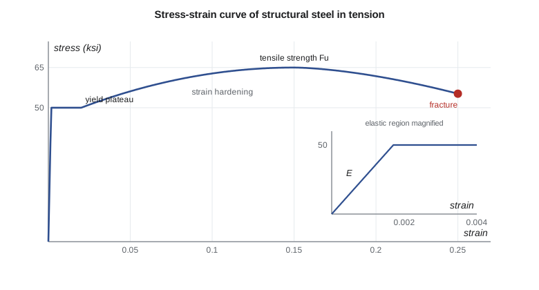
Three things on this curve matter for design. The yield stress \(F_y\) sets the strength of members that fail by yielding or by inelastic buckling. The tensile strength \(F_u\) sets the strength of net sections, bolts and welds that fail by fracture. And the long plateau and strain-hardening give ductility: a steel member can redistribute load and absorb energy long after it first yields. The plastic design of beams in lesson 5 relies on it.
Other properties are nearly the same for all structural steels: shear modulus \(G = 11{,}200\) ksi, Poisson's ratio 0.3, coefficient of thermal expansion about \(6.5 \times 10^{-6}\) per °F, and unit weight 490 lb/ft³.
Grades of steel
In the United States, structural steel is specified to ASTM standards. Each standard covers a product and gives the minimum yield and tensile strengths, chemistry and testing. The table lists the common choices. This course uses A992 for W shapes, A36 for angles and A572 Grade 50 for plates where a higher strength helps.
| Product | Common grade | Fy (ksi) | Fu (ksi) |
|---|---|---|---|
| W shapes | ASTM A992 | 50 | 65 |
| Angles, channels, plates | ASTM A36 or A572 Grade 50 | 36 or 50 | 58 or 65 |
| Rectangular HSS | ASTM A500 Grade C or A1085 | 50 | 62 or 65 |
| Pipe | ASTM A53 Grade B | 35 | 60 |
| High-strength bolts | ASTM F3125 Grade A325 | — | 120 |
| Weld metal | E70XX electrodes | — | FEXX = 70 |
HSS made to ASTM A500 may have a wall thinner than nominal, so AISC uses a design wall thickness of 0.93 times the nominal; A1085 HSS have tighter tolerances and use the nominal thickness.
Toughness and brittle fracture
A ductile steel can still fracture in a brittle way when three conditions meet: a sharp notch or crack, high tensile stress, and low temperature. Toughness, the ability to resist crack growth, is measured by the Charpy V-notch test, which records the energy absorbed in breaking a small notched bar at a given temperature. Steel becomes less tough as the temperature drops, with a transition from ductile tearing to brittle cleavage.
Most buildings are heated and their steel never sees very low temperatures, but members in unheated buildings, exterior canopies, bridges and heavy members joined by complete-joint-penetration welds in tension may need a specified Charpy energy at a low test temperature; AISC 360 requires it for the heaviest shapes and plates in such joints. Good detailing matters as much as material: avoid sharp re-entrant corners, intersecting welds and notches in tension zones.
Residual stresses
Hot-rolled shapes cool unevenly. The flange tips and the middle of the web cool first and the flange-web junctions last, and the parts that cool last end up in tension while the parts that cooled first are left in compression. These residual stresses, often 30 percent of the yield stress at the flange tips, are locked in before any load is applied. They do not change the plastic moment or the yield load of a short member, but they make parts of the section yield early under compression. That early yielding reduces the stiffness of a column and is the reason the column strength curves in lesson 4 fall below the elastic buckling curve at intermediate slenderness.
Rolled shapes and their names
The common shapes are wide-flange W shapes, HP bearing piles, standard S beams, M shapes, channels C and MC, angles L, tees WT cut from W shapes, HSS (square, rectangular and round), pipe and plate. A W shape is named by its nominal depth in inches and its weight in pounds per foot: a W21x44 is about 21 in. deep and weighs 44 lb/ft. An angle is named by its leg lengths and thickness: L4x4x3/8. An HSS is named by its outside dimensions and wall: HSS6x6x3/8.
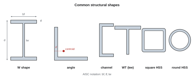
The AISC Manual tabulates for each shape its dimensions and the properties used in design: area \(A\), moments of inertia \(I_x\) and \(I_y\), elastic and plastic section moduli \(S\) and \(Z\), radii of gyration \(r_x\) and \(r_y\), the torsion constant \(J\), the warping constant \(C_w\), and the derived quantities \(r_{ts}\) and \(h_o\) used in lesson 6. AISC calls the flange width \(b_f\), flange thickness \(t_f\) and web thickness \(t_w\).
The tabulated values include the fillets where the flanges meet the web, so they are slightly larger than values computed from the flange and web plates alone. You can check a table entry, or find properties for a built-up section that is not in the tables, from the plate dimensions.
Elastic and plastic section moduli
When a beam is bent until the extreme fiber reaches the yield stress, the moment is the yield moment \(M_y = S F_y\), where \(S = I/c\) is the elastic section modulus. The beam has more strength in reserve. As the moment increases, yielding spreads inward from the extreme fibers until the whole section has yielded, half in tension and half in compression. That is the plastic moment:
For a doubly symmetric section the plastic neutral axis is at mid-depth. For a W shape bent about its strong axis,
The ratio \(Z/S\) is the shape factor. For W shapes bent about the strong axis it is about 1.10 to 1.18, because most of the material is already in the flanges; for a rectangle it is 1.5 and for bending of a W shape about its weak axis it is about 1.5 or more.
Local buckling and section classes
A wide thin flange or a deep thin web can buckle locally, rippling like a sheet of paper, before the section yields completely. Whether it does depends on the width-to-thickness ratio of each plate element and on whether the element is supported along one edge, like a flange outstand, or both edges, like a web.
AISC 360 classifies each element of a section for flexure as compact, noncompact or slender, and for axial compression as nonslender or slender. A compact section can reach \(M_p\) with enough rotation capacity for ordinary design, and AISC Appendix 1 sets stricter limits for plastic analysis. A noncompact flange or web buckles between \(M_y\) and \(M_p\), and a slender element buckles before yielding. For a flange the ratio is \(\lambda = b_f/2t_f\); for a web it is \(h/t_w\), with \(h\) the clear distance between flanges less the fillets.
| Element | Compact (λp) | Noncompact (λr) | Value for Fy = 50 ksi |
|---|---|---|---|
| Flange of a W shape, bf/2tf | 0.38√(E/Fy) | 1.0√(E/Fy) | 9.15 / 24.1 |
| Web in flexure, h/tw | 3.76√(E/Fy) | 5.70√(E/Fy) | 90.6 / 137 |
Nearly all rolled W shapes are compact in bending at 50 ksi. A few have noncompact flanges, and the AISC Manual marks them with a footnote. In axial compression, elements at or below \(0.56\sqrt{E/F_y}\) for a flange and \(1.49\sqrt{E/F_y}\) for a web are nonslender and can reach the yield load.
Worked problem
Checking table properties and section class
Owen wants to understand the Manual entry for the W21x44 he will use for the mezzanine beams (\(d = 20.7\), \(b_f = 6.50\), \(t_f = 0.450\), \(t_w = 0.350\) in.). Compute \(A\) and \(Z_x\) from the plates, compare them with the Manual values \(A = 13.0\) in² and \(Z_x = 95.4\) in³, and classify the section for flexure with \(F_y = 50\) ksi.
Show solution
- \[A = 2(6.50)(0.450) + (20.7 - 0.90)(0.350) = 5.85 + 6.93 = 12.78\ \text{in}^2\]
- \[Z_x = 6.50(0.450)(20.7 - 0.45) + \frac{0.350(19.8)^2}{4} = 59.2 + 34.3 = 93.5\ \text{in}^3\]
- Both are about 2 percent below the Manual values, the difference being the fillets.
- \[\frac{b_f}{2t_f} = \frac{6.50}{2(0.450)} = 7.2 < 0.38\sqrt{\frac{29{,}000}{50}} = 9.15 \qquad \frac{h}{t_w} \approx \frac{19.8}{0.350} = 56.6 < 3.76\sqrt{\frac{29{,}000}{50}} = 90.6\]
Answer: The computed properties confirm the Manual, and the W21x44 is compact, so it can reach \(M_p\). Use the Manual values in design.
Sofia's program repeats the calculation and classifies the four shapes used most in this course. One of them is a surprise.
import math
# Section properties of a W shape from its plate dimensions (fillets ignored)
def props(d, bf, tf, tw):
    hw = d - 2 * tf
    A = 2 * bf * tf + hw * tw
    Ix = (bf * d**3 - (bf - tw) * hw**3) / 12
    Zx = bf * tf * (d - tf) + tw * hw**2 / 4
    Iy = 2 * tf * bf**3 / 12 + hw * tw**3 / 12
    J = (2 * bf * tf**3 + hw * tw**3) / 3
    Cw = Iy * (d - tf)**2 / 4
    return A, Ix, Ix / (d / 2), Zx, Iy, J, Cw

d, bf, tf, tw = 20.7, 6.50, 0.450, 0.350   # W21x44
A, Ix, Sx, Zx, Iy, J, Cw = props(d, bf, tf, tw)
print("W21x44 from plates: A = %.2f in2, Ix = %.0f in4, Sx = %.1f in3, Zx = %.1f in3" % (A, Ix, Sx, Zx))
print("            Manual: A = 13.0 in2, Ix = 843 in4, Sx = 81.6 in3, Zx = 95.4 in3")
print("Shape factor Zx/Sx = %.2f" % (Zx / Sx))

# Width-to-thickness limits for flexure (AISC 360 Table B4.1b), Fy = 50 ksi
E, Fy = 29000, 50
lp_f, lr_f = 0.38 * math.sqrt(E / Fy), 1.0 * math.sqrt(E / Fy)
lp_w, lr_w = 3.76 * math.sqrt(E / Fy), 5.70 * math.sqrt(E / Fy)
print("Flange bf/2tf: compact <= %.2f, noncompact <= %.1f" % (lp_f, lr_f))
print("Web h/tw:      compact <= %.1f, noncompact <= %.1f" % (lp_w, lr_w))

def cls(ratio, lp, lr):
    return "compact" if ratio <= lp else ("noncompact" if ratio <= lr else "slender")

shapes = {"W21x44": (20.7, 6.50, 0.450, 0.350), "W21x50": (20.8, 6.53, 0.535, 0.380),
          "W8x31": (8.00, 8.00, 0.435, 0.285), "W12x40": (11.9, 8.01, 0.515, 0.295)}
for name, (d, bf, tf, tw) in shapes.items():
    lf = bf / (2 * tf)
    lw = (d - 2 * tf) / tw
print(f"{name}: bf/2tf = {lf:4.2f} ({cls(lf, lp_f, lr_f)}), h/tw = {lw:4.1f} ({cls(lw, lp_w, lr_w)})")W21x44 from plates: A = 12.78 in2, Ix = 826 in4, Sx = 79.8 in3, Zx = 93.5 in3
Manual: A = 13.0 in2, Ix = 843 in4, Sx = 81.6 in3, Zx = 95.4 in3
Shape factor Zx/Sx = 1.17
Flange bf/2tf: compact <= 9.15, noncompact <= 24.1
Web h/tw: compact <= 90.6, noncompact <= 137.3
W21x44: bf/2tf = 7.22 (compact), h/tw = 56.6 (compact)
W21x50: bf/2tf = 6.10 (compact), h/tw = 51.9 (compact)
W8x31: bf/2tf = 9.20 (noncompact), h/tw = 25.0 (compact)
W12x40: bf/2tf = 7.78 (compact), h/tw = 36.8 (compact)The W8x31 has a flange ratio of 9.20, just above the compact limit of 9.15, so its flange is noncompact and its flexural strength is slightly below \(M_p\). The Manual flags this shape, and lesson 8 uses it as a wall column and has to account for it.
Choosing a shape
For beams, the deepest section that fits is usually the lightest for a given moment, because \(Z\) grows with depth. Narrow-flange W shapes such as the W460 and W530 series are efficient beams. For columns, the radius of gyration about the weak axis matters, so nearly square W shapes such as the W200, W250, W310 and W360 column series, and square HSS, are efficient. Angles and tees are used for truss members and bracing, channels for edge members and stair stringers, and HSS where torsion, appearance or closed shapes are wanted.
Availability matters too. Mills roll some sizes often and others rarely, and a fabricator can buy common sizes quickly from service centers. Designers keep to common sizes and repeat them, and they check with a fabricator before choosing an unusual shape.
Common mistakes
MistakeUsing \(F_y = 36\) ksi for W shapes.
InsteadW shapes are A992 with \(F_y = 50\) ksi; A36 is now used mainly for angles, channels and plates.
MistakeUsing \(S\) where the section can develop \(Z\), or the reverse.
InsteadCompact sections use \(Z\); noncompact and slender sections have reduced strength.
MistakeTaking the full flange width as \(b\) in the flange slenderness ratio.
InsteadThe flange outstand is half the flange width.
MistakeIgnoring toughness for an unheated structure with thick welded plates.
InsteadSpecify notch-tough steel and detail to avoid notches where brittle fracture is possible.
Summary and key terms
- Structural steel has \(E = 29{,}000\) ksi, a yield plateau and strain hardening to \(F_u\); A992 W shapes have \(F_y = 50\) ksi and \(F_u = 65\) ksi.
- Yielding limit states use \(F_y\); fracture limit states use \(F_u\).
- Residual stresses from cooling cause early yielding in compression and lower the strength of intermediate columns.
- The plastic moment is \(M_p = ZF_y\); the shape factor \(Z/S\) is about 1.1 to 1.2 for W shapes in strong-axis bending.
- Compact sections reach \(M_p\); noncompact elements buckle between \(M_y\) and \(M_p\); slender elements buckle before yielding.
- The W21x44 is compact; the W8x31 has a noncompact flange.
- Yield stress
- The stress at which steel begins to deform plastically, Fy.
- Tensile strength
- The maximum engineering stress reached in a tension test, Fu.
- Yield plateau
- The range of strain over which steel yields at nearly constant stress.
- Charpy V-notch test
- An impact test that measures the energy absorbed in fracturing a notched specimen.
- Residual stress
- Stress locked into a member by uneven cooling or welding before any load is applied.
- Plastic section modulus
- Z, the first moment of the areas above and below the plastic neutral axis.
- Shape factor
- The ratio Z/S of plastic to elastic section modulus.
- Compact section
- A section whose flanges and web are stocky enough to develop the plastic moment.
Practice problems
Work each problem on paper first, then reveal the answer to check.
Compute \(M_p\) and \(M_y\) for the W21x44 using the Manual values.
Show answer
\(M_p = 95.4(50)/12 = 398\) kip·ft; \(M_y = 81.6(50)/12 = 340\) kip·ft.
What is the shape factor of a solid rectangular section?
Show answer
\(Z/S = (bh^2/4)/(bh^2/6) = 1.5\).
A built-up flange is 16 in. wide and 5/8 in. thick, \(F_y = 50\) ksi. Is it compact?
Show answer
\(\lambda = 16/1.25 = 12.8 > 9.15\) but \(< 24.1\), so noncompact.
Why do residual stresses not change \(M_p\)?
Show answer
They are self-equilibrating; once the whole section has yielded, the stress is \(F_y\) everywhere regardless of the initial pattern.
Lesson quiz · 5 questions
Score 60% or more to complete this lesson.
Create a free account to save your progress, take quizzes and earn a certificate.