
CIV-331 · Lesson 1 of 12 · 24 min
Steel structures and limit states design
Steel frames carry most of the industrial buildings, warehouses, arenas and tall office towers built in the United States. This course teaches you to design the members and connections of those frames to AISC 360, Specification for Structural Steel Buildings, with loads from ASCE 7. The first lesson sets the stage: why steel behaves the way it does, how steel buildings are organized, how load and resistance factor design (LRFD) puts safety into the numbers, and what the Kestrel Bay team will design in the steel-framed maintenance bay of the Duluth operations center.
Why build in steel
Structural steel is strong for its weight. A rolled beam can span three times as far as a timber joist of the same depth, and a steel column occupies a fraction of the floor area of a concrete column carrying the same load. Steel is also ductile: a steel member that is overloaded yields, stretches and bends visibly long before it breaks, which gives warning and lets loads shift to other parts of the structure. Ductility is the main reason steel frames perform well in earthquakes and survive local damage.
Steel members are made in a shop and erected on site. Shapes come from the mill in standard sizes, the fabricator cuts, drills and welds them, and the erector bolts them together, often in all weather. A steel frame can go up in weeks, and it can be modified later: a beam can be reinforced, a new opening framed or a mezzanine added. At the end of a building's life steel is recycled, and most structural shapes made in North America already contain a large share of recycled scrap from electric arc furnaces.
Steel has weaknesses that the designer must manage:
- Slender members and thin plates buckle. Because steel is so strong, members are slender, and stability rather than strength often controls design. Much of this course is about buckling of columns, beams and plates.
- Steel loses strength and stiffness at high temperature, so buildings that need a fire-resistance rating protect the steel with sprayed materials, boards, intumescent coatings or concrete encasement.
- Unprotected steel corrodes in wet or salty environments. Paint, galvanizing and detailing that sheds water control corrosion.
- Repeated stress cycles, such as those from a crane, can grow cracks at welds and holes. This is fatigue.
- At low temperatures, thick plates with notches or cracks can fail in a brittle way. Material toughness requirements and good detailing prevent this, which matters in an unheated building in a northern city.
How steel buildings are organized
Most steel buildings are assembled from a small set of members. Beams carry floor and roof loads in bending; girders are larger beams that carry other beams. Columns carry the beam reactions down to the foundations. Long roof spans use trusses or open-web steel joists, and a profiled steel deck spans between joists or beams, either bare on a roof or filled with concrete on a floor.
The frame must also resist lateral loads from wind and earthquakes and keep the columns from swaying. There are two main ways to do this. In a braced frame, diagonal members form vertical trusses in some bays, and the beams are connected to the columns with simple connections that transfer shear but little moment. In a moment frame, rigid beam-to-column connections make the beams and columns act together in bending. Braced frames use less steel; moment frames keep bays open for doors and windows. Many buildings use both, with braces in one direction and moment frames in the other.
Connections decide how the frame behaves. A simple shear connection, such as a pair of angles bolted to the beam web, lets the beam end rotate and is modeled as a pin. A moment connection, with the beam flanges welded or bolted to the column, is modeled as rigid. The designer chooses the connection type at the start, because the analysis model, member sizes and cost all depend on it.
Steel design standards
In the United States, the building code adopted by the state or city, nearly always based on the International Building Code (IBC), refers to ASCE 7 for loads and to AISC 360 for the design of steel members and connections. The current specification is AISC 360-22; jurisdictions that adopt the IBC a few years after each edition may still reference AISC 360-16. The provisions used in this course are essentially the same in both. Other standards fill in the details: ASTM standards for steel and bolts, AWS D1.1 for welding, the RCSC Specification for structural joints using high-strength bolts, and AISC 303, the Code of Standard Practice, which sets out the responsibilities of owners, designers, fabricators and erectors. AISC also publishes the Steel Construction Manual, with section properties, design tables and the specification with commentary. You will use its tables constantly.
LRFD and ASD
A limit state is a condition in which a structure or member stops doing its job. Ultimate limit states involve collapse or failure: yielding over a whole cross-section, fracture at a bolt hole, buckling of a column, failure of a weld. Serviceability limit states involve fitness for use: deflection that cracks partitions, floor vibration that annoys occupants, or drift that damages cladding.
AISC 360 offers two equivalent formats. In LRFD, the design strength must be at least the required strength computed from factored load combinations:
Here \(R_n\) is the nominal strength computed from specified material strengths and nominal dimensions. In LRFD, \(\phi\) is a resistance factor less than 1.0 and the loads are factored; in allowable strength design (ASD), the nominal strength is divided by a safety factor \(\Omega\) and the loads are combined without factors. AISC calibrated the two so that \(\Omega = 1.5/\phi\): \(\phi = 0.90\) corresponds to \(\Omega = 1.67\). Both give similar designs when the live load is about three times the dead load; LRFD is more economical when dead load dominates. This course uses LRFD, with ASD shown occasionally for comparison. Required strengths carry a subscript u: \(P_u\), \(M_u\), \(V_u\).
The resistance factors reflect how predictable each limit state is and how serious its failure would be. Yielding of steel is predictable and ductile, so it gets a high factor. Fracture through a net section or a weld is less predictable and gives no warning, so its factor is lower.
| Limit state | AISC 360 factor |
|---|---|
| Yielding of a gross section, member buckling, bending | φ = 0.90 |
| Fracture of a net section, block shear | φ = 0.75 |
| Shear yielding of a rolled beam web | φv = 1.00 for most rolled I-shapes |
| Bolts in shear or tension | φ = 0.75 |
| Bearing of bolts on connected material | φ = 0.75 |
| Fillet welds | φ = 0.75 |
Load combinations
ASCE 7 gives the LRFD load combinations. Each combines a principal load at its full factor with companion loads at reduced factors, and dead load is factored by 0.9 when it reduces the effect being checked:
| No. | Combination |
|---|---|
| 1 | 1.4D |
| 2 | 1.2D + 1.6L + 0.5(Lr or S or R) |
| 3 | 1.2D + 1.6(Lr or S or R) + (L or 0.5W) |
| 4 | 1.2D + 1.0W + L + 0.5(Lr or S or R) |
| 5 | 0.9D + 1.0W |
| 6 and 7 | 1.2D + Ev + Eh + L + 0.2S and 0.9D − Ev + Eh |
Serviceability is checked with service (unfactored) loads, usually the live load alone for deflection of floors, or dead plus live for total deflection. The ASD combinations, such as D + L and D + 0.75L + 0.75S, use service loads directly.
The maintenance bay
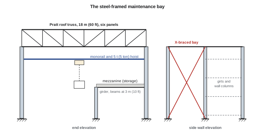
The Kestrel Bay team of Priya Raman (project lead), Owen Lachance (EI) and Sofia Martel (co-op student) designed the reinforced concrete office wing in CIV-330. The garage includes a steel-framed maintenance bay, 60 ft wide, with a mezzanine for parts storage, a monorail hoist for lifting engines, and Pratt roof trusses that you analyzed in CIV-224. This course designs its steel: the truss chords, the mezzanine beams, girders and columns, a wall column, the bracing, the monorail, and the bolted and welded connections that join them.
The mezzanine is a concrete slab on steel deck. Beams at 10 ft centers span 30 ft between edge girders, and the girders span 30 ft between columns, so each girder carries two beam reactions at its third points. The slab, deck and services weigh 65 psf, and the light storage live load is 125 psf.
Worked problem
Design loads for a mezzanine beam
Find the required moment and shear for a typical mezzanine beam: span 30 ft, spacing 10 ft, dead load 65 psf plus an assumed self-weight of 44 lb/ft, live load 125 psf.
Show solution
- Line loads on the beam:
- \[w_D = 0.065(10) + 0.044 = 0.694\ \text{kip/ft} \qquad w_L = 0.125(10) = 1.25\ \text{kip/ft}\]
- Combination 1 gives \(1.4(0.694) = 0.97\) kip/ft. Combination 2 governs:
- \[w_u = 1.2(0.694) + 1.6(1.25) = 2.83\ \text{kip/ft}\]
- \[M_u = \frac{w_u L^2}{8} = \frac{2.83(30)^2}{8} = 319\ \text{kip·ft} \qquad V_u = \frac{w_u L}{2} = 42.5\ \text{kips}\]
- For comparison, ASD with D + L gives \(w_a = 1.94\) kip/ft and \(M_a = 219\) kip·ft.
Answer: \(M_u = 319\) kip·ft and \(V_u = 42.5\) kips. Lesson 5 selects the beam.
Worked problem
Girder and truss chord forces
Find the required moment in an edge girder that carries the reactions of two beams at its third points, and the governing chord forces in the roof truss of CIV-224 (60 ft span, six 10 ft panels, 7 ft deep, dead load 0.52 kip/ft and snow 1.05 kip/ft along the truss).
Show solution
- Girder: each beam delivers \(P = 42.5\) kips, and between the third points the moment is constant:
- \[M_u = P\,\frac{L}{3} = 42.5(10) = 425\ \text{kip·ft} \quad \text{plus the girder self-weight}\]
- Truss: combination 3 with snow as the principal load gives \(w_u = 1.2(0.52) + 1.6(1.05) = 2.30\) kip/ft and panel loads \(P = 23.0\) kips. From the method of sections in CIV-224:
- \[T_{L2L3} = \frac{M_{U2}}{h} = 132\ \text{kips (tension)} \qquad C_{U2U3} = \frac{M_{L3}}{h} = 148\ \text{kips (compression)}\]
Answer: The girder moment is 425 kip·ft before self-weight; the bottom chord carries 132 kips in tension and the top chord 148 kips in compression. Lessons 3 and 6 use these forces.
Sofia keeps the load calculations in a short program so that every later lesson starts from the same numbers. If the storage load or the snow load changes, she reruns it and every member check updates.
# Maintenance bay: required strengths with ASCE 7 combinations (kips, ft)
L_beam, s_beam = 30.0, 10.0        # mezzanine beam span and spacing
D_area, L_area = 65.0, 125.0       # psf: slab on deck + services; light storage
self_wt = 0.044                    # kip/ft, assumed beam self-weight

wD = D_area * s_beam / 1000 + self_wt
wL = L_area * s_beam / 1000
lrfd = {"1.4D": 1.4 * wD, "1.2D + 1.6L": 1.2 * wD + 1.6 * wL}
print(f"wD = {wD:.3f} kip/ft, wL = {wL:.3f} kip/ft")
for name, w in lrfd.items():
    print(f"LRFD {name:12s} wu = {w:.3f} kip/ft  Mu = {w*L_beam**2/8:6.1f} kip-ft  Vu = {w*L_beam/2:5.1f} kips")
wu = max(lrfd.values())
wa = wD + wL
print(f"ASD  D + L        wa = {wa:.3f} kip/ft  Ma = {wa*L_beam**2/8:6.1f} kip-ft  Va = {wa*L_beam/2:5.1f} kips")
Vu = wu * L_beam / 2

# Edge girder: beam reactions at the third points of a 30 ft span
print(f"Girder: P = {Vu:.1f} kips at third points, Mu (before self-weight) = {Vu*L_beam/3:.1f} kip-ft")

# Roof truss (CIV-224): 60 ft span, 10 ft panels, 7 ft deep, trusses at 25 ft
wu_r = 1.2 * 0.52 + 1.6 * 1.05
P_r = wu_r * 10
R = 3 * P_r
M_U2 = R * 20 - P_r / 2 * 20 - P_r * 10
M_L3 = R * 30 - P_r / 2 * 30 - P_r * 20 - P_r * 10
print(f"Truss: wu = {wu_r:.2f} kip/ft, panel load P = {P_r:.1f} kips")
print(f"Bottom chord L2L3 tension = {M_U2/7:.1f} kips, top chord U2U3 compression = {M_L3/7:.1f} kips")wD = 0.694 kip/ft, wL = 1.250 kip/ft LRFD 1.4D wu = 0.972 kip/ft Mu = 109.3 kip-ft Vu = 14.6 kips LRFD 1.2D + 1.6L wu = 2.833 kip/ft Mu = 318.7 kip-ft Vu = 42.5 kips ASD D + L wa = 1.944 kip/ft Ma = 218.7 kip-ft Va = 29.2 kips Girder: P = 42.5 kips at third points, Mu (before self-weight) = 424.9 kip-ft Truss: wu = 2.30 kip/ft, panel load P = 23.0 kips Bottom chord L2L3 tension = 131.7 kips, top chord U2U3 compression = 148.1 kips
Ultimate and serviceability limit states in steel
Each member type has its own list of limit states, and the design checks all that apply. The table shows the ones covered in this course and where.
| Member | Main limit states | Lesson |
|---|---|---|
| Tension member | Yielding of gross section, fracture of net section, block shear | 3 |
| Column | Flexural, torsional and local buckling | 4 |
| Beam | Plastic moment, local buckling, lateral-torsional buckling, shear, web crippling, deflection | 5 to 7 |
| Beam-column | Interaction of axial load and bending, with second-order effects | 8 and 11 |
| Bolted joint | Bolt shear, bearing and tearout, slip, block shear | 9 |
| Welded joint | Weld metal shear, base metal shear | 10 |
| Frame | Sway stability, bracing strength and stiffness, drift | 11 |
Serviceability limit states use service loads. Common deflection limits are span/360 under live load for floors with plastered or brittle finishes and span/240 under total load, as given in the IBC for many members, and crane runways and monorails need stricter limits. Floor vibration matters more as steel floors become lighter; AISC Design Guide 11 covers walking vibration.
Who does what
A steel building passes through many hands. The structural engineer of record designs the members and states the connection forces on the design drawings. AISC 303 allows three options for connections: the engineer of record designs them, or delegates them to a licensed engineer working for the fabricator, or lets the fabricator select tabulated connections. A detailer prepares shop drawings showing every piece, hole and weld; the engineer of record reviews them for conformance with the design. The fabricator buys steel with mill test reports, cuts, drills and welds it, often in an AISC-certified shop, and the erector assembles the frame. Special inspection under the building code checks bolting and welding. When you design a member, you are also writing instructions for all of these people, so clear drawings and complete connection forces matter as much as correct calculations.
A good steel design is also an economical one. The cost of a steel frame depends more on the number of pieces and connections than on the weight of steel. Repeating the same beam size across a floor, choosing connections the local fabricators prefer, and avoiding stiffeners and complex welds often save more than shaving the weight of each member.
Common mistakes
MistakeMixing factored and specified loads in the same check.
InsteadStrength checks use factored loads; deflection and vibration checks use specified loads.
MistakeUsing 1.2D + 1.6L for a roof without checking the snow combination.
InsteadRoof members are often governed by combination 3, with snow as the principal load.
MistakeTreating a simple connection as rigid in the analysis, or the reverse.
InsteadThe analysis model must match the connections that will be built.
MistakeChoosing the lightest section for every member.
InsteadFewer sizes and simpler connections often cost less than a small saving in weight.
Summary and key terms
- Steel is strong, light and ductile, but slender members buckle and the material needs protection from fire, corrosion, fatigue and brittle fracture.
- Buildings combine beams, girders, columns, trusses, joists and deck; braced frames or moment frames resist lateral load.
- AISC 360 LRFD requires \(\phi R_n \ge R_u\) from the ASCE 7 combinations; ASD uses \(R_n/\Omega \ge R_a\) with \(\Omega = 1.5/\phi\).
- Resistance factors are high for ductile yielding and lower for fracture, bolts and welds.
- The mezzanine beam carries \(M_u = 319\) kip·ft and \(V_u = 42.5\) kips; the truss bottom chord carries 132 kips in tension.
- Limit state
- A condition beyond which a structure or member no longer meets a design requirement.
- Design strength
- The nominal strength multiplied by the resistance factor φ.
- Resistance factor
- A factor less than 1.0 applied to a nominal resistance to account for variability and the consequences of failure.
- Load factor
- A factor applied to a specified load to account for loads larger than expected.
- Braced frame
- A frame that resists lateral load through diagonal members acting as a vertical truss.
- Moment frame
- A frame that resists lateral load through rigid beam-to-column connections.
- Simple connection
- A connection that transfers shear but allows the beam end to rotate.
- Shop drawings
- Drawings prepared for the fabricator that show every piece, hole and weld.
Practice problems
Work each problem on paper first, then reveal the answer to check.
A roof beam spanning 25 ft at 8 ft centers carries 25 psf dead and 42 psf snow. Find \(M_u\).
Show answer
\(w_u = 1.2(0.20) + 1.6(0.336) = 0.778\) kip/ft; \(M_u = 0.778(25)^2/8 = 60.8\) kip·ft.
What safety factor \(\Omega\) corresponds to \(\phi = 0.75\)?
Show answer
\(\Omega = 1.5/0.75 = 2.00\).
Name two serviceability limit states for a steel floor.
Show answer
Deflection under live load and walking vibration.
Why might a braced frame be chosen over a moment frame?
Show answer
Bracing uses less steel and allows simple, cheap connections; moment frames are chosen where open bays are needed.
Lesson quiz · 5 questions
Score 60% or more to complete this lesson.
Create a free account to save your progress, take quizzes and earn a certificate.