
CIV-330 · Lesson 2 of 12 · 22 min
Materials and design properties
Every design equation in this course rests on a few material properties: the compressive strength of concrete, its stiffness and tensile strength, the way it creeps and shrinks over time, and the yield strength and stiffness of the reinforcing steel. CIV-230 covered how concrete is proportioned, placed and tested. This lesson collects the properties a designer actually uses, shows where the design values come from, and introduces the simplified stress block that turns the curved stress distribution of concrete into a rectangle that can be handled by hand.
Compressive strength
The specified compressive strength \(f'_c\) is the strength the designer selects and the producer must achieve. It is measured on standard cylinders, 4 × 8 in. or 6 × 12 in., moist-cured and tested at 28 days. Because test results scatter, the mix is proportioned for a higher average strength so that only a small fraction of tests fall below \(f'_c\); ACI 318 sets the acceptance criteria based on the average of three consecutive tests and on individual low results. Common design strengths are 4,000 psi for buildings, 5,000 psi or more for parking structures and exposed elements, and 8,000 psi or higher for heavily loaded columns.
Strength depends mainly on the water-to-cementitious materials ratio, the degree of curing and age. Concrete keeps gaining strength after 28 days, slowly, as long as moisture is available. Strength in a structure can be lower than in a cylinder because of less thorough compaction and curing, which is one reason the resistance side of design carries its own safety factor.
The stress-strain curve
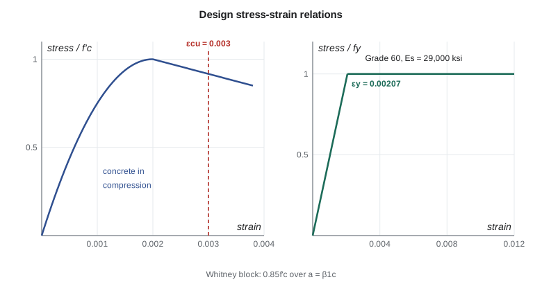
A concrete cylinder loaded in compression responds almost linearly up to about 40 percent of its strength. Microcracks then grow at the paste-aggregate interfaces, the curve bends over, and the peak stress is reached at a strain of about 0.002. Beyond the peak the stress falls as the cracks join up. For flexural design, ACI 318 assumes that the extreme compression fiber of a member reaches its capacity at a strain \(\varepsilon_{cu} = 0.003\). Higher-strength concrete is more brittle, with a steeper descending branch, which is why the stress block depth factor decreases as \(f'_c\) increases.
A widely used mathematical model for the rising branch is the Hognestad parabola,
with \(\varepsilon_0 \approx 0.002\). It is useful for checking strain-compatibility analyses and for understanding the shape of the stress distribution in a beam, but the design codes replace it with a simpler rectangle.
Modulus of elasticity
The slope of the stress-strain curve near the origin is the modulus of elasticity \(E_c\), needed for deflections, cracked section analysis and column slenderness. ACI 318 gives an expression that depends on strength and density, which for normal-weight concrete simplifies to
with \(w_c\) in lb/ft³ between 90 and 160. The expressions are averages; the actual modulus depends strongly on the stiffness of the coarse aggregate and can differ by 20 percent or more. When deflections are critical, the modulus can be measured on cylinders from trial batches.
The modular ratio \(n = E_s/E_c\) converts steel areas into equivalent concrete areas for elastic analysis of cracked sections. It is about 8 for normal-strength concrete and falls as the concrete gets stronger.
Tensile strength
Concrete tensile strength is used in only a few places: the cracking moment for deflection calculations, minimum reinforcement and some shear provisions. ACI 318 takes the modulus of rupture, the flexural tensile strength, as
where \(\lambda\) is 1.0 for normal-weight concrete and between 0.75 and 0.85 for lightweight concretes. The same factor reduces shear and bond strengths, because cracking in lightweight aggregate passes through the weaker aggregate particles.
The direct tensile strength is lower than the modulus of rupture, roughly 0.33 to 0.4 times the square root of the compressive strength in SI units. Design never relies on concrete tensile strength to carry a load permanently; it only predicts when cracking begins.
Time-dependent behavior: creep and shrinkage
Concrete under sustained stress keeps deforming. This creep strain develops quickly at first and then more slowly, over several years, and can reach two to three times the initial elastic strain. The ratio of creep strain to elastic strain is the creep coefficient. Creep is greater for concrete loaded at an early age, for wetter mixes, for thin members and in dry air.
Shrinkage is the reduction in volume as concrete dries, independent of load. Typical ultimate drying shrinkage strains are 400 to 800 microstrain. When shrinkage is restrained by reinforcement, supports or adjacent construction, tensile stresses develop and the concrete cracks; this is why every slab carries shrinkage and temperature reinforcement and why long slabs need control joints.
For design, creep and shrinkage show up mainly in long-term deflections. ACI 318 multiplies the immediate deflection under sustained load by a factor that depends on the duration of loading and on the amount of compression reinforcement, as lesson 5 shows. Creep also redistributes load from concrete to steel in columns, and it reduces the stiffness used in slender column calculations.
The equivalent rectangular stress block
At the ultimate limit state in flexure, the compression zone of a beam contains the whole curved stress-strain relation, from zero at the neutral axis to the peak and beyond near the extreme fiber. Integrating that curve every time would be tedious. Whitney showed in the 1930s that the curved distribution can be replaced by a uniform stress over a reduced depth, chosen so that the resultant force and its location are the same.
In ACI 318 the uniform stress is \(0.85f'_c\), acting over a depth \(a = \beta_1 c\), where \(c\) is the depth to the neutral axis. The depth factor depends on the concrete strength:
Only \(\beta_1\) changes with strength; the 0.85 intensity factor is kept for all strengths. ACI 318 requires at least 2,500 psi for structural concrete and sets higher minima for seismic and durability cases.
| f'c (psi) | β1 | Ec (psi) | fr (psi) |
|---|---|---|---|
| 3,000 | 0.85 | 3,122,000 | 411 |
| 4,000 | 0.85 | 3,605,000 | 474 |
| 5,000 | 0.80 | 4,031,000 | 530 |
| 6,000 | 0.75 | 4,415,000 | 581 |
| 8,000 | 0.65 | 5,098,000 | 671 |
Compare the Canadian code, which uses an ultimate strain of 0.0035 and lets both the intensity and the depth of the block fall with strength. For ordinary strengths the two approaches give flexural capacities within a few percent of each other, because flexural strength of an under-reinforced beam depends mostly on the steel.
Reinforcing steel
Reinforcing bars in the United States are made to ASTM A615 (carbon steel) or ASTM A706 (low-alloy, weldable, with controlled yield and tensile properties). The usual grade is 60, with \(f_y = 60{,}000\) psi; Grades 80 and 100 are increasingly used in columns and walls. A706 bars are required for welding and in special seismic systems. The modulus of elasticity is \(E_s = 29{,}000{,}000\) psi, so the yield strain is \(\varepsilon_y = f_y/E_s = 0.00207\) for Grade 60.
Inch-pound bar designations give the nominal diameter in eighths of an inch for sizes up to #8. A #8 bar is 1.000 in. in diameter with an area of 0.79 in². Sizes #9, #10 and #11 have the areas of the old square bars of 1, 1⅛ and 1¼ in., so their diameters do not follow the eighths rule. Bars are deformed by ribs rolled into the surface and are usually stocked in 60 ft lengths. Welded wire reinforcement in sheets or rolls is used in slabs on grade and thin toppings.
| Bar | Diameter (in.) | Area (in²) | Weight (lb/ft) |
|---|---|---|---|
| #3 | 0.375 | 0.11 | 0.376 |
| #4 | 0.500 | 0.20 | 0.668 |
| #5 | 0.625 | 0.31 | 1.043 |
| #6 | 0.750 | 0.44 | 1.502 |
| #7 | 0.875 | 0.60 | 2.044 |
| #8 | 1.000 | 0.79 | 2.670 |
| #9 | 1.128 | 1.00 | 3.400 |
| #10 | 1.270 | 1.27 | 4.303 |
| #11 | 1.410 | 1.56 | 5.313 |
For design, steel is idealized as elastic-perfectly plastic: stress equals \(E_s\varepsilon_s\) up to yield and stays at \(f_y\) for larger strains. Real bars strain-harden beyond a yield plateau, which adds reserve strength that design does not count on, except in seismic capacity design where the expected over-strength of the bars must be considered.
Cover and bar spacing
Concrete cover protects bars from corrosion and fire and allows bond to develop. ACI 318 sets minimum cover by exposure and member type: 1.5 in. for interior beams and columns (to the stirrups or ties), 0.75 in. for interior slabs with #11 bars and smaller, 1.5 to 2 in. for concrete exposed to weather, and 3 in. for concrete cast against earth. ACI 362 recommends 2 in. top cover for parking decks exposed to de-icing chemicals, and fire resistance requirements in the building code may require more.
The clear distance between parallel bars must be at least the bar diameter, 1 in. and 4/3 of the maximum aggregate size, so that concrete can flow between them and bond can develop. When bars are placed in layers, the upper layer is placed directly above the lower one with a clear distance of at least 1 in. between layers.
Worked problem
Modular ratio and cracking stress for the office concrete
Find \(E_c\), the modular ratio \(n\) and the modulus of rupture for the 4,000 psi office concrete, and the stress block factor.
Show solution
- \[E_c = 57{,}000\sqrt{4000} = 3{,}605{,}000\ \text{psi}\]
- \[n = \frac{E_s}{E_c} = \frac{29{,}000{,}000}{3{,}605{,}000} = 8.04\]
- \[f_r = 7.5(1.0)\sqrt{4000} = 474\ \text{psi}\]
- \[\beta_1 = 0.85 \quad (f'_c \le 4000\ \text{psi})\]
Answer: \(E_c = 3{,}605\) ksi, \(n = 8.0\), \(f_r = 474\) psi and \(\beta_1 = 0.85\). With the garage concrete at 5,000 psi, \(\beta_1\) drops to 0.80.
Worked problem
Selecting bars for a required area
A beam needs 2.58 in² of tension steel and is 14 in. wide with 1.5 in. cover and #3 stirrups. Choose bars that fit in one layer.
Show solution
- Four #8 bars give \(4 \times 0.79 = 3.16\) in², about 22 percent more than needed. Three #9 bars give 3.00 in², closer to the requirement.
- Clear spacing for four #8 bars:
- \[s = \frac{14 - 2(1.5 + 0.375) - 4(1.0)}{3} = 2.08\ \text{in.}\]
- The minimum is the largest of \(d_b = 1.0\) in., 1 in., and \(4/3 \times 0.75 = 1.0\) in. for 3/4 in. aggregate. 2.08 in. is adequate.
Answer: Either 3 #9 or 4 #8 works; the team chooses 4 #8 because four bars across the width distribute cracks better and give more room for the beam-column joint bars.
import math
# ACI 318 design properties for normal-weight concrete (psi)
def beta1(fc):
    return min(0.85, max(0.65, 0.85 - 0.05 * (fc - 4000) / 1000))
print("  f'c   beta1   Ec=57000rt   fr=7.5rt")
for fc in (3000, 4000, 5000, 6000, 8000):
    Ec = 57000 * math.sqrt(fc)
    fr = 7.5 * 1.0 * math.sqrt(fc)        # lambda = 1.0
    print(f"{fc:6d}  {beta1(fc):5.3f} {Ec:12.0f} {fr:10.0f}")
# Modular ratio for the 4000 psi office concrete
Es = 29_000_000
n = Es / (57000 * math.sqrt(4000))
print(f"modular ratio n for 4000 psi: {n:.2f}")
# Inch-pound bar sizes: number = diameter in eighths of an inch
areas = {3: 0.11, 4: 0.20, 5: 0.31, 6: 0.44, 7: 0.60, 8: 0.79, 9: 1.00, 10: 1.27, 11: 1.56}
for b, A in areas.items():
    db = {9: 1.128, 10: 1.270, 11: 1.410}.get(b, b / 8)
print(f"#{b}: db = {db:.3f} in., A = {A:.2f} in2, 4 bars = {4*A:.2f} in2")f'c beta1 Ec=57000rt fr=7.5rt 3000 0.850 3122019 411 4000 0.850 3604997 474 5000 0.800 4030509 530 6000 0.750 4415201 581 8000 0.650 5098235 671 modular ratio n for 4000 psi: 8.04 #3: db = 0.375 in., A = 0.11 in2, 4 bars = 0.44 in2 #4: db = 0.500 in., A = 0.20 in2, 4 bars = 0.80 in2 #5: db = 0.625 in., A = 0.31 in2, 4 bars = 1.24 in2 #6: db = 0.750 in., A = 0.44 in2, 4 bars = 1.76 in2 #7: db = 0.875 in., A = 0.60 in2, 4 bars = 2.40 in2 #8: db = 1.000 in., A = 0.79 in2, 4 bars = 3.16 in2 #9: db = 1.128 in., A = 1.00 in2, 4 bars = 4.00 in2 #10: db = 1.270 in., A = 1.27 in2, 4 bars = 5.08 in2 #11: db = 1.410 in., A = 1.56 in2, 4 bars = 6.24 in2
Sofia's program reproduces the table above and adds a useful observation: the full density-dependent expression for the modulus and the simplified one agree within a few percent for normal concrete, so the simple form is acceptable for most designs.
Common mistakes
MistakeUsing a constant \(\beta_1 = 0.85\) for all concrete strengths.
Instead\(\beta_1\) drops by 0.05 per 1,000 psi above 4,000 psi, to a minimum of 0.65.
MistakeTreating the modulus of elasticity from the code formula as exact.
InsteadIt is an average estimate; aggregate type can change it by 20 percent or more.
MistakeRelying on concrete tensile strength to resist a sustained load.
InsteadTensile strength only predicts cracking; reinforcement must carry tension.
MistakeAssuming a #10 bar is 10/8 in. in diameter.
Instead#9 to #11 do not follow the eighths rule; a #10 bar is 1.270 in. in diameter.
Summary and key terms
- \(f'_c\) is the specified 28-day cylinder strength; design properties are derived from it.
- ACI 318 uses an ultimate concrete strain of 0.003 in flexure and a Whitney block of intensity \(0.85f'_c\) and depth \(\beta_1 c\).
- \(E_c = 57{,}000\sqrt{f'_c}\) psi and \(f_r = 7.5\lambda\sqrt{f'_c}\) for normal-weight concrete.
- Creep and shrinkage increase deflections over time and cause cracking when restrained.
- Grade 60 bars have \(f_y = 60\) ksi, \(E_s = 29{,}000\) ksi and \(\varepsilon_y = 0.00207\); standard bars run from #3 to #18.
- Cover and clear spacing rules protect the steel and let concrete flow around it.
- Specified compressive strength
- The 28-day cylinder strength used in design, written f'c.
- Modulus of rupture
- The flexural tensile strength of concrete, used to find the cracking moment.
- Modular ratio
- The ratio of the steel modulus to the concrete modulus.
- Creep
- Increase in strain with time under sustained stress.
- Shrinkage
- Reduction in volume of concrete as it dries, independent of load.
- Equivalent rectangular stress block
- A uniform compressive stress over a reduced depth that replaces the curved stress distribution at ultimate.
- Yield strength
- The stress at which reinforcing steel begins to deform plastically.
- Concrete cover
- The thickness of concrete between the surface and the nearest reinforcement.
Practice problems
Work each problem on paper first, then reveal the answer to check.
Find \(\beta_1\) for 7,000 psi concrete.
Show answer
\(\beta_1 = 0.85 - 0.05(3) = 0.70\).
What is the modulus of rupture of 5,000 psi lightweight concrete with \(\lambda = 0.75\)?
Show answer
\(f_r = 7.5(0.75)\sqrt{5000} = 398\) psi.
How many #6 bars give at least 1.70 in²?
Show answer
Four, giving 1.76 in².
Why does the stress block depth factor fall as concrete strength rises?
Show answer
High-strength concrete has a more linear rising branch and a steeper drop, so the stress distribution is more triangular and its resultant acts lower relative to the neutral axis depth.
What is the yield strain of Grade 80 bars?
Show answer
\(80/29{,}000 = 0.00276\).
Lesson quiz · 5 questions
Score 60% or more to complete this lesson.
Create a free account to save your progress, take quizzes and earn a certificate.