
CIV-330 · Lesson 4 of 12 · 22 min
Doubly reinforced beams and T-beams
Lesson 3 dealt with the simplest section: a rectangle with steel on the tension side only. Real beams are rarely that simple. Most floor beams are cast monolithically with the slab, so in positive bending the slab acts as a wide compression flange and the beam is a T-section. And some beams carry bars near the compression face as well, either because the depth is limited or because the bars are needed for other reasons. This lesson extends flexural theory to both cases and then generalizes it into a strain-compatibility routine that handles any arrangement of bars.
Why add compression reinforcement?
Steel placed near the compression face of a beam is called compression reinforcement, and a beam with both tension and compression steel is called doubly reinforced. There are several reasons to provide it:
- Depth is limited. When the architect or the mechanical services fix the depth, the moment may need so much tension steel that the section falls out of the tension-controlled range. Compression steel takes part of the compression, so the neutral axis rises, \(\varepsilon_t\) increases and \(\phi\) returns to 0.90.
- Ductility. Compression steel reduces the depth of the compression zone and so increases the steel strain at failure. Seismic design requires it at beam ends for this reason.
- Long-term deflection. Compression steel restrains creep of the compression zone. The long-term deflection multiplier in lesson 5 falls as the compression steel ratio rises.
- Moment reversal and detailing. Continuous beams have negative moment over supports and positive moment at midspan, so bars are present near both faces anyway. Stirrups also need longitudinal bars in their top corners to wrap around.
Analysis of a doubly reinforced section
Add a compression steel area \(A'_s\) at depth \(d'\) from the compression face. The forces at nominal strength are the concrete block \(C_c = 0.85f'_c a b\), the compression steel force \(C_s\) and the tension \(T = A_s f_y\). The compression steel occupies space that would otherwise hold concrete in the stress block, so its net force is
Horizontal equilibrium \(C_c + C_s = T\) gives one equation in the unknown \(c\). If both steels yield, it is linear and solved directly. If the compression steel does not yield, which is common in shallow beams where \(d'\) is a large fraction of \(c\), \(f'_s\) depends on \(c\) and the equation becomes a quadratic. Once \(c\) is known, moments about the tension steel give the resistance:
The tension-controlled and minimum strain limits of lesson 3 apply to the extreme tension steel as before. Adding compression steel is the standard way to satisfy them when the depth cannot change.
Worked problem
Depth-limited office beam
A 20 ft beam under the mechanical room on the second floor must be no deeper than 20 in. so ducts can pass below it. It is 14 in. wide, \(f'_c = 4{,}000\) psi, and \(M_u = 300\) kip·ft. Tension bars are #8 in two layers (3 bars at 17.5 in. and 3 at 15.5 in., centroid \(d = 16.5\) in.); compression bars are #8 at \(d' = 2.5\) in.
Show solution
- Singly reinforced with 6 #8: equilibrium gives \(c = 7.03\) in., \(\varepsilon_t = 0.0045\), so the section is in the transition zone with \(\phi = 0.85\), and \(\phi M_n = 272\) kip·ft. That is less than 300 kip·ft, and adding tension steel would reduce \(\phi\) further.
- Add 2 #8 top bars. Assume the compression steel yields and check: equilibrium gives \(c = 4.8\) in., for which \(\varepsilon'_s = 0.003(4.8 - 2.5)/4.8 = 0.0014 < 0.00207\). It does not yield, so set \(f'_s = 29{,}000(0.003)(c - 2.5)/c\) ksi and solve
- \[0.85(4)(0.85c)(14) + 1.58\Big(87\,\frac{c - 2.5}{c} - 3.4\Big) = 6(0.79)(60) = 284.4\]
- \[c = 5.35\ \text{in.}, \quad f'_s = 46.4\ \text{ksi}, \quad a = 4.55\ \text{in.}\]
- \[C_c = 216.6\ \text{kips}, \qquad C_s = 1.58(46.4 - 3.4) = 67.9\ \text{kips}\]
- \[M_n = 216.6(16.5 - 2.28) + 67.9(16.5 - 2.5) = 3081 + 951 = 4032\ \text{kip·in.} = 336\ \text{kip·ft}\]
- Extreme tension steel: \(\varepsilon_t = 0.003(17.5 - 5.35)/5.35 = 0.0068 > 0.00507\), so \(\phi = 0.90\) and \(\phi M_n = 302\) kip·ft \(\ge 300\).
Answer: Use 6 #8 bottom in two layers and 2 #8 top. The compression bars do not yield, but they raise the strength by 11 percent, mostly by restoring \(\phi\) from 0.85 to 0.90.
T-beams and the effective flange
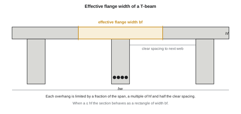
When a beam is cast with the slab, the slab on each side of the web carries compression in positive bending. Away from the web the compressive stress dies out because of shear deformation of the flange (shear lag), so the codes replace the real, uneven stress distribution with a uniform stress over an effective flange width \(b_f\).
ACI 318 limits the effective overhang on each side of the web of a T-beam to the least of 8 times the slab thickness, half the clear distance to the next web, and one eighth of the span. For an L-beam with the slab on one side only, the overhang is limited to 6 times the slab thickness, half the clear distance to the next web, and one twelfth of the span.
Two cases arise. If the depth of the stress block is within the flange, \(a \le h_f\), the compression zone is a rectangle of width \(b_f\), and the section behaves exactly like a rectangular beam of width \(b_f\): the concrete below the neutral axis plays no part in flexural strength. Because the flange is wide, this is by far the usual case for floor beams in positive bending.
If the block extends into the web, \(a > h_f\), split the compression into the flange overhangs, \(C_f = 0.85f'_c(b_f - b_w)h_f\) acting at \(h_f/2\), and the web, \(C_w = 0.85f'_c b_w a\) acting at \(a/2\). Equilibrium with \(T\) gives \(a\), and moments about the tension steel give \(M_n\). This happens with narrow flanges, heavily reinforced beams, or precast double tees.
In negative bending over a support the flange is in tension and cracks, and the compression is in the narrow web at the bottom. The section is then a rectangle of width \(b_w\), and the web width controls the amount of steel that can be used. The negative moment bars, however, may be spread across part of the flange.
ACI 318 requires part of the negative moment steel to be distributed over the effective flange width or a width equal to one tenth of the span, whichever is smaller, to control cracking in the slab, with some longitudinal steel in the outer parts of the flange.
Worked problem
Garage T-beam
The upper parking level of the garage is an 8 in. slab on beams at 20 ft centers, each with a 16 in. web and an overall depth of 28 in. (\(d = 25.5\) in.). The beams span 30 ft, simply supported on the garage frames, with \(f'_c = 5{,}000\) psi. Service loads are \(D = 2.53\) kip/ft (slab, web and 10 psf of services) and \(L = 40\) psf × 20 ft = 0.80 kip/ft. Design the positive moment steel.
Show solution
- Factored load and moment:
- \[w_u = 1.2(2.53) + 1.6(0.80) = 4.32\ \text{kip/ft} \qquad M_u = \frac{4.32(30)^2}{8} = 486\ \text{kip·ft}\]
- Effective overhang: least of \(8(8) = 64\), \((240 - 16)/2 = 112\) and \(360/8 = 45\) in. So \(b_f = 16 + 2(45) = 106\) in.
- Try 5 #9, \(A_s = 5.00\) in², assuming the block is in the flange:
- \[a = \frac{5.00(60)}{0.85(5)(106)} = 0.67\ \text{in.} < h_f = 8\ \text{in.}\]
- \[\phi M_n = 0.90(5.00)(60)\Big(25.5 - \frac{0.67}{2}\Big)\frac{1}{12} = 566\ \text{kip·ft} \ge 486\]
- The strain is enormous, \(\varepsilon_t = 0.089\), so the section is tension-controlled. Four #9 would give 454 kip·ft, not enough.
- Minimum steel uses the web width: \(3\sqrt{5000}(16)(25.5)/60{,}000 = 1.44\) in², well below 5.00 in².
Answer: Use 5 #9 bottom bars. The neutral axis is less than an inch deep, inside the slab, so the T-beam is very ductile.
The example shows why T-beams are efficient: the wide flange supplies all the compression with a very short block, so the lever arm is almost the full effective depth. The web exists mainly to carry shear, house the tension bars and give depth. Over the supports, where the moment is negative in a continuous beam, the same web must carry the compression on its own, and that is usually what sets its width.
Strain compatibility for any section
The hand methods above all follow the same steps: guess the neutral axis depth, compute the strain at each bar, convert strains to stresses, sum the forces, and adjust the guess until the forces balance. A short program can do this for any number of bar layers and for rectangular, T or L shapes. Sofia writes one routine that handles all the beams in this lesson; lesson 10 extends it to columns by allowing a net axial force.
# Strain-compatibility flexural strength for T and doubly reinforced sections, ACI 318
Es, ecu = 29e6, 0.003

def strength(fc, fy, bw, bf, hf, layers):
    """layers: list of (area in2, depth from top in.). Returns c, phi, phiMn (kip-ft), eps_t."""
    b1 = min(0.85, max(0.65, 0.85 - 0.05 * (fc - 4000) / 1000))
    def forces(c):
        a = b1 * c
        Af = bf * min(a, hf) + bw * max(a - hf, 0.0)
        yf = (bf * min(a, hf) ** 2 / 2 + bw * max(a - hf, 0) * (hf + a) / 2) / Af
        Cc = 0.85 * fc * Af
        F, M = Cc, Cc * yf               # moment about the top face
        strains = []
        for As, y in layers:
            es = ecu * (c - y) / c         # + compression
            fs = max(-fy, min(fy, Es * es))
            f = As * fs
            if es > 0 and y < a:           # bar inside the stress block displaces concrete
                f -= 0.85 * fc * As
            F += f; M += f * y; strains.append(es)
        return F, M, strains
    lo, hi = 0.05, 100.0
    for _ in range(100):                  # bisection on axial force = 0
        c = (lo + hi) / 2
        F, M, s = forces(c)
        lo, hi = (lo, c) if F > 0 else (c, hi)
    F, M, s = forces(c)
    dt = max(y for _, y in layers)
    et = ecu * (dt - c) / c                # net tensile strain in the extreme layer
    ety = fy / Es
    phi = 0.90 if et >= ety + 0.003 else (0.65 if et <= ety else 0.65 + 0.25 * (et - ety) / 0.003)
    return c, phi, phi * (-M) / 12000, et

# Garage T-beam: f'c 5000, bw 16, h 28, d 25.5, slab 8 in., simple span 30 ft, beams at 20 ft
ln, sw, hf, bw = 30 * 12.0, 20 * 12.0 - 16, 8.0, 16.0
over = min(8 * hf, sw / 2, ln / 8)
bf = bw + 2 * over
print(f"T-beam: effective overhang = {over:.1f} in., bf = {bf:.0f} in.")
for n in (4, 5):
    c, phi, M, et = strength(5000, 60000, bw, bf, hf, [(n * 1.00, 25.5)])
    print(f"  {n} #9: c = {c:.2f} in. (flange {hf:.0f}), eps_t = {et:.4f}, phi = {phi:.2f}, phiMn = {M:.0f} kip-ft")
c, phi, M, et = strength(5000, 60000, bw, bw, hf, [(5 * 1.00, 25.5)])
print(f"  web only, 5 #9: c = {c:.2f} in., eps_t = {et:.4f}, phi = {phi:.2f}, phiMn = {M:.0f} kip-ft")

# Depth-limited office beam: b 14, h 20, bars in two layers, d' = 2.5, Mu = 300 kip-ft
print("Doubly reinforced beam, f'c 4000, b 14, h 20:")
for top, bot in ((0, 5), (0, 6), (2, 6), (3, 6)):
    layers = [(top * 0.79, 2.5)] if top else []
    nl = (bot + 1) // 2
    layers += [(nl * 0.79, 17.5), ((bot - nl) * 0.79, 15.5)]
    c, phi, M, et = strength(4000, 60000, 14, 14, 20, layers)
print(f" top {top} #8, bottom {bot} #8: c = {c:.2f} in., eps_t = {et:.4f}, phi = {phi:.3f}, phiMn = {M:.0f} kip-ft")T-beam: effective overhang = 45.0 in., bf = 106 in. 4 #9: c = 0.67 in. (flange 8), eps_t = 0.1119, phi = 0.90, phiMn = 454 kip-ft 5 #9: c = 0.83 in. (flange 8), eps_t = 0.0889, phi = 0.90, phiMn = 566 kip-ft web only, 5 #9: c = 5.51 in., eps_t = 0.0109, phi = 0.90, phiMn = 524 kip-ft Doubly reinforced beam, f'c 4000, b 14, h 20: top 0 #8, bottom 5 #8: c = 5.86 in., eps_t = 0.0060, phi = 0.900, phiMn = 253 kip-ft top 0 #8, bottom 6 #8: c = 7.03 in., eps_t = 0.0045, phi = 0.850, phiMn = 272 kip-ft top 2 #8, bottom 6 #8: c = 5.35 in., eps_t = 0.0068, phi = 0.900, phiMn = 302 kip-ft top 3 #8, bottom 6 #8: c = 4.79 in., eps_t = 0.0080, phi = 0.900, phiMn = 305 kip-ft
The output confirms the hand calculations and adds two useful comparisons. If the slab were ignored and the 16 in. web designed as a rectangle, the same 5 #9 would give 524 kip·ft, with a neutral axis more than six times deeper: the flange matters. And for the office beam, the program shows how three top bars instead of two raise the strength only slightly, because the strength gain comes mostly from keeping \(\phi\) at 0.90.
Choosing between options
When a beam cannot be made deeper, designers have several choices, each with costs. Wider beams use more concrete and formwork but keep the steel simple. Higher-strength concrete helps a little in flexure and more in shear and stiffness. Compression steel is efficient when the beam has top bars anyway, which is true near supports and in seismic regions. Two layers of tension steel reduce the effective depth and complicate placing. In the operations center the team uses compression steel in the few depth-limited beams and keeps every other beam singly reinforced at midspan.
Common mistakes
MistakeAssuming the compression steel always yields.
InsteadCheck \(\varepsilon'_s\); in shallow beams the compression steel often stays elastic, and its stress must come from strain compatibility.
MistakeForgetting the concrete displaced by the compression bars.
InsteadSubtract \(0.85f'_c A'_s\) from the compression steel force.
MistakeUsing the full slab width as the flange.
InsteadLimit each overhang by span, flange thickness and half the clear web spacing.
MistakeUsing the flange width in negative bending.
InsteadOver supports the flange is in tension; the compression zone is the web, of width \(b_w\).
Summary and key terms
- Compression steel is used when depth is limited, to improve ductility, to reduce long-term deflection, and for detailing.
- Its net force is \(A'_s(f'_s - 0.85f'_c)\), with \(f'_s\) from strain compatibility.
- A T-beam with the block in the flange behaves like a rectangle of width \(b_f\); otherwise split the compression into flange overhangs and web.
- Effective overhangs are limited to 8\(h_f\), half the clear web spacing, and span/8.
- The garage T-beam needs 5 #9 for \(M_u = 486\) kip·ft; the 20 in. deep office beam needs 6 #8 plus 2 #8 top for 300 kip·ft.
- A strain-compatibility routine handles any bar arrangement and is the basis of column interaction diagrams.
- Doubly reinforced beam
- A beam with reinforcement near both the tension and compression faces.
- Compression reinforcement
- Longitudinal bars near the compression face that carry part of the compressive force.
- Effective flange width
- The width of slab assumed to act with a beam web under uniform compressive stress.
- Shear lag
- The non-uniform distribution of flange stress caused by in-plane shear deformation.
- T-beam
- A beam whose web is cast with a slab on both sides, forming a T-shaped section.
- L-beam
- An edge beam with slab on one side only.
- Strain compatibility
- Analysis that finds bar stresses from a linear strain distribution and enforces equilibrium.
- Displaced concrete
- The concrete replaced by compression bars inside the stress block, which must not be counted twice.
Practice problems
Work each problem on paper first, then reveal the answer to check.
Find the effective flange width of an interior T-beam spanning 24 ft, web 14 in., slab 6 in., webs at 10 ft centers.
Show answer
Overhang = least of 48, 53, 36 in. = 36 in.; \(b_f = 14 + 72 = 86\) in.
A T-beam has \(a\) = 1.2 times the flange thickness. Which method applies?
Show answer
The block enters the web, so split the compression into flange overhangs and web.
Why is compression steel in shallow beams often below yield?
Show answer
\(d'\) is a large fraction of \(c\), so the strain at the compression bars is small.
In the office beam example, what is the stress in the top bars?
Show answer
46.4 ksi, below the 60 ksi yield stress.
Why does the web width matter more over the supports of a continuous T-beam?
Show answer
The flange is in tension there, so the narrow web carries all the compression.
Lesson quiz · 5 questions
Score 60% or more to complete this lesson.
Create a free account to save your progress, take quizzes and earn a certificate.