
BAS-230 · Lesson 7 of 12 · 24 min
Chilled water plant sequences
▶ Video coming soon A video version of this lesson is on the way.
On Tuesday, October 6, Callie had stood in Ninefield Tower's penthouse watching the chilled water plant return water only 6.3 °F warmer than it left, where the design called for 10 °F. The next evening, Wednesday, October 7, Sophie put Ninefield's 1998 chilled water plant sequence on the table, with the draft paragraphs Quillon was writing for the retro-commissioning in the spring of 2027 beside it. "A chiller plant is three or four sequences talking to each other," she said. "Chillers, primary pumps, secondary pumps and the tower. When one of them is wrong, the others try to make up for it, and you see the symptom somewhere else. Your low delta-T is a good example."
The parts of a chilled water plant
Ninefield's plant has two water-cooled chillers of 200 tons each, one cooling tower, and a primary-secondary pumping arrangement. Each chiller has its own constant-speed primary pump that runs whenever the chiller runs. Two secondary pumps on VFDs, one duty and one standby, push water out to the air handler coils and control a differential pressure in the system. Between the primary and secondary loops is a short pipe called the decoupler or common pipe, which lets the two loops run at different flows.
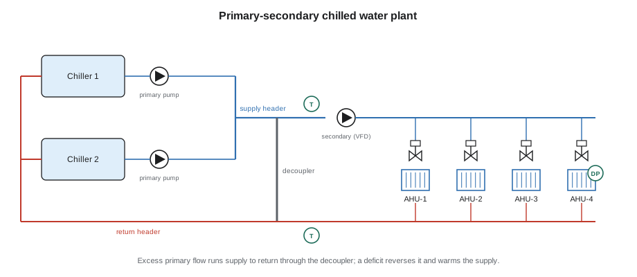
The sequence for a plant like this answers a set of questions. When is the plant enabled? Which chiller leads? When does the second chiller start and stop? What chilled water temperature does the plant supply, and is it reset? How are the secondary pumps controlled? What happens when a chiller or pump fails? And what protects the chillers, which have their own controls and their own limits, from the automation system asking for something they cannot do?
Plant enable and the chiller's own controls
As with boilers, a chiller has its own controller that manages its compressor, its safeties and its capacity. The automation system typically enables the chiller, gives it a chilled water supply setpoint, and monitors its status and alarms, often over a BACnet or Modbus interface as BAS-310 describes. It must also enable the chiller's pumps and the tower before the chiller starts, and prove their flow, because a chiller started without flow through its evaporator or condenser will trip on its own flow switches or, worse, freeze its evaporator.
Ninefield's plant was enabled when any of its four air handlers requested chilled water and the outdoor air was above 54 °F. Below that, the air handlers' economizers carried the load. Because the economizers could carry most of the load in cool weather, the plant ran from about mid-April to mid-November. On Monday, October 19, as BAS-130 described, Callie had watched Ilona's maintenance contractor swing the chillers over for the winter while Prakash tested the secondary pump failover; in a mild autumn the plant rarely needs more than one chiller.
| Step | Action | Proof |
|---|---|---|
| 1 | Start the lead chiller's primary pump | Evaporator flow switch or pump status |
| 2 | Start the condenser water pump and enable the tower | Condenser flow switch |
| 3 | Enable the chiller with its supply setpoint | Chiller running status |
| 4 | Enable the secondary pumps on differential pressure control | Pump status and system pressure |
| 5 | Release the air handler cooling valves to their loops | Coil leaving air temperatures fall |
Staging chillers
With two chillers, the second must start when one cannot carry the load and stop when one can. Sequences stage chillers by load, by temperature, by flow, or a combination. A load-based rule starts the lag chiller when the lead runs above a high fraction of its capacity for a sustained time. A temperature-based rule starts it when the supply temperature stays above setpoint, which means the lead cannot keep up. In a primary-secondary plant there is a third trigger, flow: when the secondary loop needs more water than the running primary pumps supply.
| Rule | Sample setting |
|---|---|
| Stage up on load | Lead chiller above 90 in 100 of capacity for 15 minutes |
| Stage up on temperature | Supply above setpoint by 2 °F for 10 minutes |
| Stage up on flow | Reverse flow in the decoupler for 10 minutes |
| Stage down | Load could be carried by one chiller below 80 in 100 for 15 minutes |
| Minimum run and off times | Per the chiller manufacturer, typically 15 to 30 minutes |
Why low delta-T matters
The heat a chilled water flow carries depends on the flow and the temperature difference between supply and return. When the return water comes back only slightly warmer than it left, the plant must pump more water to carry the same load. In a primary-secondary plant, if the secondary flow exceeds the primary flow of the chillers that are running, water flows backward through the decoupler, warm return water mixes into the supply, and the supply temperature rises. The sequence then starts the second chiller, not because the load needs it but because the flow does. This is the low delta-T problem, and Ninefield had it.
Worked problem
Flow needed at design and low delta-T
One Ninefield chiller is carrying 160 tons, 80 in 100 of its capacity. Using gpm = tons × 24 ÷ ΔT, how much chilled water flow does that load need at the design delta-T of 10 °F? At the measured 6.3 °F? Each chiller's primary pump moves 480 gpm.
Show solution
- At 10 °F: 160 × 24 ÷ 10 = 384 gpm, less than one primary pump's 480 gpm.
- At 6.3 °F: 160 × 24 ÷ 6.3 = 610 gpm, more than one primary pump moves.
- Deficit with one chiller: 610 − 480 = 130 gpm, which flows backward through the decoupler.
Answer: At design delta-T one chiller carries this load easily. At 6.3 °F the coils need 610 gpm, and 130 gpm of warm return water mixes into the supply. The plant must run a second chiller at low load just to supply flow.
Worked problem
How much the mixing warms the supply
In the case above, the chiller supplies 44 °F and the return water is 6.3 °F warmer, at 50.3 °F. If 480 gpm of 44 °F water mixes with 130 gpm of 50.3 °F return water flowing backward through the decoupler, what temperature reaches the coils?
Show solution
- Mixed temperature: (480 × 44 + 130 × 50.3) ÷ 610.
- (21,120 + 6,539) ÷ 610 = 45.3 °F.
Answer: The coils receive about 45.3 °F instead of 44 °F. Warmer supply water makes the coil valves open further, which raises the flow and lowers the delta-T again. The problem feeds itself, which is why it must be fixed at the coils, not at the plant.
The causes of low delta-T are almost always at the coils: three-way valves that bypass supply water straight into the return, coils with valves stuck open or oversized, dirty coils, air handlers with supply air setpoints set too low, and differential pressure setpoints set too high. BAS-110 found two of these at Ninefield: the two oldest penthouse air handlers still had three-way valves, and one air handler's supply air setpoint had been lowered to 50 °F. Quillon's draft retro-commissioning sequence addressed all of them: two-way valves, with the valve schedule BAS-120 described; supply air reset as in lesson 4; and differential pressure reset as in lesson 9.
Chilled water supply temperature reset
A colder chilled water supply removes more moisture and lets coils and pipes be smaller, but it makes the chillers work harder. Raising the supply temperature when the load is light saves chiller energy, typically a little for each kelvin of reset. It also needs more flow for the same coil load, which costs pump energy and can worsen delta-T. Good sequences therefore reset chilled water temperature from coil requests, raising it only while every coil is still satisfied, and keep it at design whenever humidity control needs cold water.
Quillon's draft for Ninefield reset the chilled water supply between 44 °F and 50 °F by trim and respond from the air handlers' cooling valve requests, with a dehumidification limit that held it at design when the return air humidity was high. Sophie marked the values as SAMPLE in the draft, to be confirmed with the engineer who would stamp the final sequence. She also coordinated it with the supply air reset from lesson 4: the air handlers reset their supply air first, and the plant raises the water temperature only when the air handlers' valves are no longer near fully open.
Primary-only variable flow
Many newer plants have no primary-secondary split. Instead, a single set of variable-speed pumps sends water through the chillers and out to the coils, and the flow through the chillers varies with the load. This saves a set of pumps and avoids the decoupler problem, but the sequence must protect each chiller's minimum evaporator flow, typically given by the manufacturer. A bypass valve between supply and return opens only when the system flow falls below the minimum for the chillers that are running, and the chillers must stage with care, because adding a chiller suddenly halves the flow through the one already running.
Worked problem
Minimum flow in a primary-only plant
If Ninefield were converted to primary-only variable flow, and the chiller manufacturer required at least 40 in 100 of the 480 gpm design flow through a running chiller, what is the minimum flow the bypass must maintain with one chiller running?
Show solution
- Minimum flow: 0.40 × 480 = 192 gpm.
Answer: With one chiller running, the bypass valve opens whenever the coils together draw less than 192 gpm, so the chiller never sees less than its minimum.
The Ninefield retro-commissioning did not propose this conversion. Sophie explained that the existing primary-secondary plant would work well once the coils were fixed, and that a conversion was a larger project for the day the chillers were replaced. The waterside economizer study, which BAS-110 listed, was the other large idea on the list, and lesson 8 explains what it involves.
Failure responses in the chilled water plant
Chilled water plants have more ways to fail than heating plants, and each failure needs a written response. The chillers protect themselves through their own controls, and the automation sequence's job is to notice, keep cooling going with what is left and tell someone.
| Failure | Typical sequence response |
|---|---|
| Chiller trips or fails to start | Lock it out, stage on the next chiller, alarm; keep the failed chiller locked out until reset |
| Primary or condenser water pump fails to prove | Start the standby pump if there is one, otherwise stage off the dedicated chiller |
| Secondary pump fails | Start the standby secondary pump and alarm |
| Chilled water supply sensor fails | Stop resetting the setpoint; return to the design supply temperature |
| Flow switch or flow meter fails | Treat as no flow for chiller enable; alarm rather than run blind |
| Cooling tower or condenser water fault | Unload or stop chillers as their own controls require; alarm |
Two points need special care. First, a chiller that trips should not be restarted by the automation system in a tight loop; most chillers enforce their own restart delay, and the sequence should add a lockout after repeated failures so that a real fault is not hammered every few minutes. Second, when a sensor that drives a reset fails, the reset should stop and the plant should return to its design values. Running colder water than needed costs energy; running warmer water than the coils can use, on a bad reading, costs comfort and humidity control.
Ninefield's 1998 sequence said almost nothing about failures. Prakash's secondary pump failover test in October was the first time anyone had checked that the standby pump actually took over, and it did, after a 20 second delay that the draft now records as an adjustable value instead of a number buried in the program.
Common mistakes
MistakeStarting a chiller before its pumps and tower are proven.
InsteadProve evaporator and condenser flow first, then enable the chiller.
MistakeTreating low delta-T as a plant problem.
InsteadLook for three-way valves, stuck or oversized valves, low supply air setpoints and high pressure setpoints at the coils.
MistakeResetting chilled water up without checking the coils.
InsteadReset from coil requests and hold design temperature when dehumidification needs it.
MistakeStaging chillers with no time delays.
InsteadUse load, temperature or flow triggers with delays and margins, and respect minimum run and off times.
MistakeLetting a primary-only plant fall below a chiller's minimum flow.
InsteadOpen the bypass to hold each running chiller's minimum evaporator flow.
Summary and key terms
- A chilled water plant sequence covers enable, start order, staging, supply temperature, pumps, failures and interfaces with the chillers' own controls.
- Pumps and towers must be proven before a chiller is enabled.
- Chillers stage on load, temperature or flow, with delays and margins.
- Heat carried equals flow times delta-T, so low delta-T needs more flow for the same load.
- In a primary-secondary plant, low delta-T causes reverse decoupler flow, warmer supply and extra chillers.
- The causes of low delta-T are at the coils, and so are the fixes.
- Chilled water reset saves chiller energy but must be coordinated with coils and humidity; primary-only plants must protect minimum chiller flow.
- Primary-secondary
- A pumping arrangement with constant primary pumps for the chillers and variable secondary pumps for the building.
- Decoupler
- The short common pipe between primary and secondary loops.
- Delta-T
- The difference between return and supply water temperatures.
- Low delta-T syndrome
- A plant returning water too cool, needing extra flow and extra chillers.
- Chiller staging
- Logic that starts and stops chillers as the load changes.
- Chilled water reset
- Changing the chilled water supply setpoint according to demand.
- Primary-only variable flow
- A plant with one set of variable-speed pumps through chillers and coils.
- Minimum evaporator flow
- The lowest flow a chiller's manufacturer allows through its evaporator.
Practice problems
Work each problem on paper first, then reveal the answer to check.
A 120-ton load at a delta-T of 9 °F needs how much water? Use tons × 24 ÷ ΔT.
Show answer
120 × 24 ÷ 9 = 320 gpm.
The same load at 5.4 °F?
Show answer
120 × 24 ÷ 5.4 = 533 gpm.
Primary flow 480 gpm at 44 °F, reverse decoupler flow 80 gpm at 50 °F. Supply to coils?
Show answer
(480 × 44 + 80 × 50) ÷ 560 = 44.9 °F.
Name three coil-side causes of low delta-T.
Show answer
Any three of three-way valves, stuck or oversized valves, dirty coils, low supply air setpoints and high differential pressure setpoints.
Minimum flow 35 in 100 of a 640 gpm design flow. What must the bypass maintain?
Show answer
0.35 × 640 = 224 gpm.
Lesson quiz · 5 questions
Score 60% or more to complete this lesson.
Create a free account to save your progress, take quizzes and earn a certificate.