
AUTO-120 · Lesson 6 of 12 · 21 min
Variable valve timing and cylinder deactivation
Gord Haney's pickup is back two weeks after the bushing job, this time with a complaint that worries him more. On the highway it has started to tick, and twice the check engine light has flashed for a moment before going out. Marty listens with a stethoscope on the driver's side valve cover while Kiran watches the scan tool. The tick is there, light and fast, and the scan tool shows a stored misfire count on cylinder 1. “Cylinder 1 is one of the cylinders this engine shuts off on the highway,” Marty says. “Before you can understand what's wrong with it, you need to understand the parts that change the valve train while the engine runs.”
Lesson 4 described a valve train with fixed timing, lift and duration. Most modern engines vary at least one of these while they run. This lesson explains variable valve timing, which moves the camshafts relative to the crankshaft; variable valve lift; and cylinder deactivation, which stops some cylinders' valves from opening at all. It also explains how a technician reads these systems on a scan tool and why all of them depend on the engine's oil.
Why fixed valve timing is a compromise
A camshaft with fixed timing is designed for one set of conditions. At low engine speed the air moves slowly, and the intake valve should close soon after BDC so the piston does not push air back out. At high speed the air's momentum keeps it flowing into the cylinder well after BDC, so a later intake closing fills the cylinder better. At idle, valve overlap lets exhaust flow back into the intake, making the idle rough; at part load, some overlap is useful, because the exhaust gas left in the cylinder dilutes the next charge, lowers combustion temperature and reduces nitrogen oxide emissions, much like an exhaust gas recirculation valve. No single fixed timing is best for all of these.
Variable valve timing, VVT, solves the problem by turning each camshaft a few tens of degrees ahead of or behind its base position while the engine runs. The engine control module chooses the position from engine speed, load, temperature and other inputs, using maps written by the manufacturer. The result is more torque across the speed range, better economy, lower emissions and a smoother idle from the same engine.
Cam phasers and oil control valves
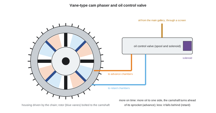
On most engines, VVT is done by a cam phaser, an oil-operated actuator built into the camshaft sprocket. The common vane type has an outer housing driven by the timing chain or belt and an inner rotor bolted to the camshaft. Vanes on the rotor divide the space inside the housing into pairs of chambers. Pumping oil into the chambers on one side of each vane turns the rotor, and the camshaft, ahead of the sprocket, advancing it; filling the other side retards it. Holding oil in both sides locks the camshaft in position. A spring-loaded locking pin holds the rotor at its base position when oil pressure is low, such as at start-up.
The oil is directed by an oil control valve, OCV, also called a VVT solenoid. It is a spool valve moved by an electric solenoid that the control module pulses on and off many times a second; the proportion of on time, the duty cycle, sets the spool's position and so how much oil goes to each side of the phaser. On some engines the OCV is screwed into the head; on others it is the center bolt of the phaser itself. A fine mesh screen protects the OCV's passages from debris.
Camshaft position sensors read toothed or notched wheels on each camshaft, and the crankshaft position sensor reads a wheel on the crankshaft. From these signals the control module knows exactly where each camshaft is relative to the crankshaft. It compares the actual position with the position it asked for, the desired position, and adjusts the OCV duty cycle to close the gap. If it cannot, because the phaser does not respond, the OCV is stuck or the timing chain has stretched, it sets a code for cam timing over-advanced, over-retarded or slow to respond, or a correlation code.
Reading VVT on a scan tool
Every VVT system can be checked with a scan tool that shows the desired and actual angle of each camshaft, the OCV duty cycle and engine oil temperature. At a warm idle the camshafts are usually at their base positions, and the actual angle should equal the desired angle within a degree or two. When the engine is raised to about 2,000 to 2,500 rpm, the module commands a change, and the actual angle should follow the desired angle smoothly within a fraction of a second. Many scan tools can also command a phaser directly, which lets the technician see whether it moves and whether the engine's idle changes as it does.
# Does the bank 1 intake phaser follow its command? (scan tool samples, 0.25 s apart)
desired = [0, 0, 0, 12, 18, 22, 25, 25, 25, 25, 25, 25]     # degrees of advance commanded
actual  = [0, 0, 1,  3,  7, 11, 15, 18, 20, 21, 21, 21]      # degrees of advance measured
limit = 5                                                     # example limit on error once settled, degrees
errors = [d - a for d, a in zip(desired, actual)]
print("time   desired  actual  error")
for i, (d, a, e) in enumerate(zip(desired, actual, errors)):
    print(f"{i * 0.25:4.2f} s  {d:6}  {a:6}  {e:5}")
settled = errors[-4:]
print(f"error after settling: {sum(settled) / len(settled):.1f} degrees ->", "phaser OK" if max(settled) <= limit else "phaser slow or not reaching its command")time desired actual error 0.00 s 0 0 0 0.25 s 0 0 0 0.50 s 0 1 -1 0.75 s 12 3 9 1.00 s 18 7 11 1.25 s 22 11 11 1.50 s 25 15 10 1.75 s 25 18 7 2.00 s 25 20 5 2.25 s 25 21 4 2.50 s 25 21 4 2.75 s 25 21 4 error after settling: 4.2 degrees -> phaser OK
Here the phaser moves in the right direction but too slowly and never reaches its command, falling four degrees short. The causes, in rough order of likelihood, are oil level or condition, a sticking or partly blocked OCV or its screen, low oil pressure, a worn phaser that leaks oil past its vanes, and a stretched chain that has already retarded the camshaft so far that the phaser cannot catch up. The order of testing follows the same list: check the oil first, then the OCV, then the phaser and chain.
A phaser can also make a noise. If its locking pin does not engage when the engine is shut off, the rotor is free to rattle against its stops until oil pressure builds at the next start, giving a brief knock or rattle at the front of the engine. This sounds very like a worn chain tensioner, and on some engines both happen together. The capstone in Lesson 12 shows how Marty and Kiran separate the two on the Lindqvists' van.
Variable valve lift
Some engines also change how far and how long the valves open. The simplest systems switch between two cam profiles: a mild profile for low speed and economy and a high-lift profile for power. They do this with rockers or tappets that can be locked together or unlocked by an oil-pressure-operated pin, so the valve follows either the small lobe or the large one. Honda's VTEC was an early well-known example, and many other manufacturers use similar two-step systems. More complex systems vary lift continuously with an electric motor and an extra linkage, which lets the engine control its airflow with the valves instead of the throttle.
For technicians, the important point is that almost all of these systems are operated by engine oil through small passages, pins and solenoids. They need the right oil, at the right level and pressure, and they are among the first parts to show problems when oil changes are neglected.
Cylinder deactivation
At a steady highway cruise, a large engine needs only a fraction of its power. Running all its cylinders at light load is inefficient, because the throttle must be nearly closed, and the pistons waste energy pulling air past it; these are called pumping losses. Cylinder deactivation shuts off some of the cylinders, so the remaining ones work harder with the throttle more open, and fuel economy improves.
Gord's 2013 pickup has General Motors' Active Fuel Management, AFM. At light load it can switch from eight cylinders to four by deactivating cylinders 1 and 7 on one bank and 4 and 6 on the other. The lifters for these cylinders are special two-part lifters with a spring-loaded pin. Normally the pin locks the two parts together and the lifter works like any other. When the control module commands four-cylinder mode, solenoids in a valve lifter oil manifold under the intake manifold send oil to the eight deactivation lifters; the oil pushes the pins in, the outer part of each lifter follows the cam lobe while the inner part stays still, and the valves stay closed. Fuel injection to those cylinders stops at the same time. The burned gas trapped in the closed cylinders acts as an air spring, so little energy is lost compressing it.
Newer trucks of this family use Dynamic Fuel Management, which can deactivate any combination of cylinders in many patterns and changes them continually as load varies. Other manufacturers have their own systems, such as cylinder deactivation on some V6 engines, and on some four-cylinder engines two cylinders can be shut off. The principles are the same: special lifters or rockers that can be switched off by oil pressure, controlled by solenoids and the engine control module.
# How much fuel does cylinder deactivation save on a highway trip? (illustrative figures)
trip = 370                       # mi of highway driving
base_use = 18.0                   # mpg with all eight cylinders running
share_in_v4 = 0.60                  # fraction of the trip spent in four-cylinder mode
saving_in_v4 = 0.10                 # fuel saved while in four-cylinder mode (example)
v8_only = trip / base_use
with_afm = v8_only * (1 - share_in_v4 * saving_in_v4)
print(f"all cylinders: {v8_only:.1f} gal; with deactivation: {with_afm:.1f} gal")
print(f"saved {v8_only - with_afm:.1f} gal on this trip ({share_in_v4 * saving_in_v4 * 100:.0f} %)")all cylinders: 20.6 gal; with deactivation: 19.3 gal saved 1.2 gal on this trip (6 %)
Fuel economy is given in miles per gallon, so the fuel used is the distance divided by the economy. The saving looks small on one trip, but over the life of a fleet of trucks it adds up, which is why manufacturers use these systems to meet fuel economy and greenhouse gas standards.
When deactivation lifters fail
Deactivation lifters have more moving parts than ordinary lifters and depend on a small, clean supply of oil to work. A lifter whose pin sticks, whose inner parts wear, or whose roller seizes and stops turning on the cam lobe can fail to open its valve or open it only partly, and a failed roller can wipe out the lobe. The usual symptoms are a tick from the valve cover, a misfire on one of the deactivation cylinders that may come and go, and in time a code for that cylinder or for the lifter oil manifold circuit. Lifter failures on these General Motors engines have been the subject of many customer complaints and of a class-action lawsuit filed in the United States, and the manufacturer has published service information on diagnosing them.
The diagnosis must be careful, because a tick and a misfire have many possible causes, from a spark plug to an injector. On Gord's truck, Marty and Kiran will use the tests in Lesson 10 to find out whether cylinder 1's valves are opening, and if they find a failed lifter, they will need the procedures in Lesson 11 to remove the cylinder head and replace it. If one deactivation lifter has failed, the others have lived the same life on the same oil, so the repair on a high-mileage engine like Gord's usually includes all the lifters on that bank or the whole set, the lifter guides, and an inspection of the camshaft lobes.
Customers sometimes ask whether they can simply turn the system off. Some aftermarket devices and engine calibrations disable cylinder deactivation, but they change the vehicle's emissions and fuel economy from what it was certified for and may affect its warranty; Ridgeline does not install them, and Marty explains to customers that the repair, not a bypass, is what Ridgeline will quote. What the shop can recommend is the oil and oil change interval that the manufacturer specifies, because clean oil of the right viscosity is what keeps these lifters working.
Worked problem
Reading Gord's scan data
On a road test, the scan tool shows Gord's truck switching between eight and four cylinders on the highway. The misfire counter for cylinder 1 rises only in eight-cylinder mode, and the tick is heard at all speeds. What does this suggest, and what should come next?
Show solution
- In four-cylinder mode cylinder 1 is deactivated, so it cannot misfire; the misfire appears only when it should be firing.
- A tick at all speeds suggests a mechanical problem in the valve train rather than an ignition or fuel fault.
- Together these point toward cylinder 1's valve train, possibly a lifter that is not fully opening a valve, but they do not prove it.
- Next, swap the cylinder 1 coil with another cylinder's and check whether the misfire moves, then perform the compression, leak-down and running tests in Lesson 10 before recommending any repair.
Answer: The data point toward cylinder 1's valve train; confirm with ignition swaps and compression tests before quoting a repair.
Common mistakes
MistakeReplacing an oil control valve without checking the oil.
InsteadCheck oil level, condition and specification first.
MistakeJudging a phaser by its angle at idle only.
InsteadCommand a change and watch the actual angle follow the desired angle.
MistakeAssuming a start-up rattle is always the chain.
InsteadA phaser whose locking pin does not engage can rattle too.
MistakeReplacing one failed deactivation lifter on a high-mileage engine.
InsteadConsider the whole bank or set, and inspect the camshaft.
MistakeInstalling devices that disable deactivation.
InsteadRepair the system and maintain the oil as specified.
Summary and key terms
- Variable valve timing moves the camshafts relative to the crankshaft to suit speed and load.
- A vane-type cam phaser is turned by oil directed by a pulsed oil control valve; a locking pin holds it at start-up.
- The control module compares desired and actual cam angles; scan data shows whether a phaser follows its command.
- Variable lift systems switch cam profiles with oil-operated pins.
- Cylinder deactivation closes the valves of some cylinders at light load to reduce pumping losses.
- All of these systems depend on clean oil of the right specification at the right pressure.
- Variable valve timing
- A system that changes camshaft timing while the engine runs.
- Cam phaser
- An oil-operated actuator in the cam sprocket that advances or retards the camshaft.
- Oil control valve
- A solenoid-operated spool valve that directs oil to a cam phaser.
- Duty cycle
- The percentage of time a pulsed solenoid is switched on.
- Pumping losses
- Energy used to draw air past a partly closed throttle.
- Cylinder deactivation
- Shutting off fuel and keeping the valves closed in some cylinders at light load.
- Deactivation lifter
- A two-part lifter that can be unlocked by oil pressure so its valve stays closed.
Practice problems
Work each problem on paper first, then reveal the answer to check.
What does advancing the intake camshaft do to the intake valve's opening and closing?
Show answer
Both happen earlier in the cycle.
Which component holds a vane phaser at its base position at start-up?
Show answer
The spring-loaded locking pin.
Name three causes of a phaser that is slow to reach its commanded angle.
Show answer
Low or dirty oil, a sticking or blocked OCV or screen, low oil pressure, a worn phaser or a stretched chain.
Why are the deactivated cylinders' valves kept closed rather than open?
Show answer
Trapped gas acts as a spring, so little energy is lost, and no cold air is pumped through the cylinders to the catalytic converter.
Lesson quiz · 5 questions
Score 60% or more to complete this lesson.
Create a free account to save your progress, take quizzes and earn a certificate.