
ARCH-130 · Lesson 11 of 12 · 24 min
Building services overview
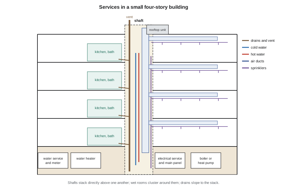
By April, the Lake Street building is closed in, and the inside is a tangle of services. Sheet metal ducts hang from the floor above, plastic and copper pipes snake through holes in the joists, bundles of cable are clipped along the walls, and red sprinkler pipes run at the ceiling with heads at regular intervals. In a narrow room at the center of each floor, a vertical shaft carries the main pipes and ducts from the mechanical room in the basement to the roof. The mechanical engineer meets the class there. 'Every one of these has to fit in a ceiling space you architects want to make as thin as possible,' she says, smiling. 'And they all have to line up from floor to floor. If the shaft on the third floor is a meter to the left of the one on the second, someone has a very bad day.' Wren realizes that the plans she drew last term had no shafts at all.
What building services are
Building services are the systems that make a building habitable and usable: heating, ventilation and air conditioning (HVAC); plumbing for water supply and drainage; electrical power, lighting and communications; fire protection; and vertical transportation by elevators and escalators. They are designed by mechanical and electrical engineers, but they shape the architecture: they need rooms, shafts, ceiling spaces, roof space and openings in the envelope, and they account for a large share of a building's cost, typically a third or more in an office or hospital, and much of its energy use and maintenance over its life. An architect who understands services early can give them the space they need and keep them from spoiling the design.
In the United States, services are governed by model codes such as the International Mechanical Code, the International Plumbing Code or the Uniform Plumbing Code, on which Minnesota's plumbing code is based, the National Electrical Code (NFPA 70) and NFPA standards for sprinklers and fire alarms, each adopted by the states.
Heating
In a cold climate, heating is the largest energy use in most buildings. Heat is produced by burning a fuel, by electric resistance or by a heat pump, and distributed by air or water.
- A furnace heats air by burning natural gas or by electric elements and distributes it through ducts to registers in each room, with return ducts bringing air back. It is the most common system in houses in the Upper Midwest.
- A boiler heats water, which is pumped through pipes to radiators, baseboard convectors or tubes embedded in floors (radiant floor heating), a hydronic system. Water carries far more heat than air for the same volume, so pipes are much smaller than ducts.
- A heat pump moves heat rather than making it, using a refrigeration cycle run in reverse: it extracts heat from outdoor air, the ground or water and delivers it indoors, and in summer it can run the other way to cool. Because it moves heat, it can deliver two to four units of heat for each unit of electricity it uses. Cold-climate air-source heat pumps now work at outdoor temperatures well below 0 °F, though their output and efficiency fall as it gets colder, and ground-source or geothermal heat pumps draw stable heat from the earth through buried loops.
Heat pumps powered by low-carbon electricity are the main route to reducing the carbon emissions of heating, and many jurisdictions are encouraging them. In Minnesota, the electricity grid is becoming lower in carbon as coal plants close and wind and solar grow, improving the case for heat pumps.
The size of the heating system follows from the heat loss of the building on a design winter day: the heat conducted through each part of the envelope, which is its area times its U-value times the temperature difference, plus the heat needed to warm the outdoor air that leaks or is brought in. The script below estimates the design heat loss of the boathouse if it became a heated warming hut.
# Design heat loss of the boathouse as a heated warming hut
t_in, t_design = 65.0, -15.0           # deg F indoors and design outdoor temperature
dT = t_in - t_design
parts = {                               # name: (area ft2, U-factor Btu/h ft2 F)
    "walls":   (534, 0.044),
    "windows": (86, 0.18),
    "roof":    (465, 0.032),
    "floor":   (384, 0.044),
}
total = 0.0
for name, (A, U) in parts.items():
    q = A * U * dT
    total += q
    print(f"{name:8s} {A:4d} ft2 x U {U:5.3f} x {dT:.0f} F = {q:6.0f} Btu/h")
volume, ach = 4000.0, 0.5              # ft3 and air changes per hour of leakage and ventilation
q_air = 0.018 * ach * volume * dT      # Btu/h (0.018 Btu per ft3 F for air)
total += q_air
print(f"air      {q_air:6.0f} Btu/h")
print(f"Design heat loss about {total:,.0f} Btu/h, or {total / 3412:.1f} kW")walls 534 ft2 x U 0.044 x 80 F = 1880 Btu/h windows 86 ft2 x U 0.180 x 80 F = 1238 Btu/h roof 465 ft2 x U 0.032 x 80 F = 1190 Btu/h floor 384 ft2 x U 0.044 x 80 F = 1352 Btu/h air 2880 Btu/h Design heat loss about 8,540 Btu/h, or 2.5 kW
A heater of about 10,000 Btu/h would keep the hut warm on the coldest night, about the power of a kitchen oven. But the hut's door will open every few minutes as skaters come and go, letting in cold air, so a real design would allow for that, perhaps with a vestibule.
Ventilation and air conditioning
People need fresh air to dilute the carbon dioxide, moisture, odors and pollutants produced indoors. Older buildings were ventilated by leakage and by opening windows; airtight modern buildings need deliberate, controlled ventilation. In houses, the IRC requires whole-house mechanical ventilation when the house is airtight, and in cold states it is often provided by a heat recovery ventilator (HRV), which exhausts stale air from kitchens and bathrooms and supplies fresh air to bedrooms and living rooms, passing the two streams through a heat exchanger so that the outgoing air warms the incoming air. An energy recovery ventilator (ERV) also transfers some moisture. Kitchens and bathrooms also need local exhaust fans.
Larger buildings use air handling units, large boxes of fans, filters, coils and dampers in a mechanical room or on the roof, connected to supply and return ducts. Variable air volume systems adjust the airflow to each zone. Many newer buildings separate ventilation from heating and cooling: a dedicated outdoor air system delivers just enough fresh air, while radiant panels, fan coils or heat pumps in each space handle the temperature. Air conditioning cools and dehumidifies air with a refrigeration cycle; in Minneapolis summers can be hot and humid, and well-designed shading and ventilation reduce the cooling needed.
Ducts are big. Air carries little heat per unit volume, so moving enough of it to heat, cool and ventilate a building takes large ducts, which must run through ceilings, shafts and walls. A rough rule for sizing is to divide the airflow by an acceptable air velocity, lower in occupied spaces to keep noise down.
# Rough duct size from airflow and velocity
for name, cfm, v in [("branch to a bedroom", 50, 600), ("main supply, apartment", 500, 900), ("main supply, office floor", 6000, 1500)]:
    area = cfm / v                             # ft2 (velocity in ft per minute)
    d = (4 * area / 3.1416) ** 0.5 * 12        # in, round duct
print(f"{name:26s} {cfm:5d} cfm at {v:4d} fpm -> area {area:5.3f} ft2, round duct about {d:4.1f} in")branch to a bedroom 50 cfm at 600 fpm -> area 0.083 ft2, round duct about 3.9 in main supply, apartment 500 cfm at 900 fpm -> area 0.556 ft2, round duct about 10.1 in main supply, office floor 6000 cfm at 1500 fpm -> area 4.000 ft2, round duct about 27.1 in
A main duct for an office floor can be close to 3 feet across, which is why the space between the ceiling and the floor above in an office building is often 3 feet or more deep, and why architects and engineers agree on duct routes long before the drawings are finished.
Plumbing
Plumbing has two separate systems. The supply system brings water under pressure from the city main or a well, through a meter and a shut-off valve, to the fixtures. Cold water branches to every fixture; part of it is heated in a water heater and distributed in a separate hot water system. Because it is under pressure, supply piping can run in any direction and in small sizes, of copper, cross-linked polyethylene (PEX) or other plastics. In tall buildings, pumps boost the pressure for upper floors.
The drainage system carries waste water away by gravity, so its pipes are larger and must slope continuously downward, typically ¼ inch per foot for small horizontal drains. Every fixture has a trap, a U-shaped bend that holds water and blocks sewer gases from entering the building. Every trap needs a vent, a pipe that lets air into the drainage system so that flowing water does not siphon the trap dry; the vents join and pass through the roof. Together these are called the drainage, waste and vent (DWV) system. Vertical drainage pipes are called stacks. Cleanouts give access to clear blockages. Rainwater from roofs is collected by a separate storm drainage system or led to the ground.
Because drainage relies on gravity, it is the hardest service to route: a drain under a long floor needs a lot of depth, and fixtures should be grouped near stacks. Architects stack bathrooms and kitchens above one another in apartment buildings and place them back to back, so that pipes are short and run straight down.
Electrical systems
Electrical power arrives from the utility through a service connection, overhead or underground, to a meter and a main switch, then to a panel, or distribution board, where circuit breakers protect individual circuits. In US houses, the service is 120/240 volts, typically 100 to 200 amperes; larger buildings receive higher voltages, such as 277/480 volts, transformed down for use. Circuits feed lighting, receptacles and equipment, with special protection where water is present, such as ground-fault circuit interrupters near sinks and outdoors, and arc-fault protection in living areas.
Large buildings have electrical rooms on each floor or group of floors, emergency generators or batteries for life safety systems, and increasingly, electric vehicle charging, rooftop solar arrays and battery storage. Lighting is a major part of electrical design and energy use; efficient LED fixtures, daylight, controls that switch off lights in empty or sunny spaces and good interior surfaces have greatly reduced lighting energy. Low-voltage systems carry data, telephone, security, fire alarm signals and building controls, and need their own pathways and rooms.
Fire protection
Fire protection combines passive and active measures. Passive measures are part of the building: fire separations, walls and floors with a fire-resistance rating that divide the building into compartments; protected exit stairs; fire-rated doors; fire stopping, sealing the openings where services pass through rated walls and floors; and non-combustible or protected materials. Active measures respond to a fire: smoke alarms and fire alarm systems that warn occupants, automatic sprinklers that spray water on a fire near where it starts, standpipes that give firefighters water connections on each floor, and smoke control systems.
Sprinklers are among the most effective life-safety measures ever introduced. Each sprinkler head contains a glass bulb or fusible link that breaks at a set temperature, opening only that head, so water is released only where the fire is. They are now required in most new multi-unit residential buildings and many others, and they allow larger and taller buildings, more glass and longer exit distances. Their piping, the riser, valves and fire department connection, must be planned from the start.
Every service that passes through a fire separation is a potential path for fire and smoke. Pipes, ducts and cables through rated walls and floors must be fire-stopped with tested systems, and ducts through rated assemblies need fire dampers that close in a fire.
Vertical transportation
Elevators are essential in buildings of more than a few stories and are required for accessibility in many. Hydraulic elevators push the car up with a piston and are economical for low buildings. Traction elevators hang the car on steel ropes or belts over a motor-driven sheave with a counterweight and are used for taller buildings; modern machine-room-less traction elevators place a compact motor in the shaft, saving a rooftop room. Elevators need a shaft, or hoistway, a pit below the lowest stop and an overhead space above the highest, and the shaft often forms part of the building's structure and fire separations. Their number and speed are set by the expected traffic, using the kind of trip-time calculation seen in ARCH-121.
Making space for services
Services need space in four places: plant rooms for the main equipment, such as boilers, chillers, air handlers, water heaters, electrical switchgear and sprinkler valves, often in the basement and on the roof; vertical shafts, which carry pipes, ducts and cables between floors and should stack directly above one another; horizontal distribution, in ceiling spaces, raised floors or bulkheads; and outdoor space for equipment, intakes, exhausts and utility connections, with intakes kept away from exhausts, parking and loading areas. An early rule of thumb is that shafts and plant rooms may take something like 5 to 10% of the floor area, more for laboratories and hospitals; the engineers will give better numbers as the design develops.
Coordination is the art of fitting all this together with the structure. Ducts must cross beams, drains must keep their slope, sprinkler heads must clear lights and ducts, and everything must be reachable for maintenance. Today, coordination is done in three-dimensional building information models (BIM), where clashes between systems can be found on screen before they are found on site, a topic of ARCH-210. Even so, the architect's early decisions, about floor-to-floor heights, the position of cores and shafts, and the grouping of wet rooms, matter most.
Worked problem
Placing services in a small apartment building
Joon-ho is designing a three-story building with two apartments on each floor. Each apartment has a kitchen and a bathroom. Where should they go, and what space should he reserve?
Show solution
- Place the kitchens and bathrooms of the two apartments back to back on each side of a shared wall, so they can share a plumbing wall and a drainage stack.
- Stack them directly above the same rooms on the floors below, so the stacks and vents run straight down to the basement.
- Reserve a small vertical shaft beside the shared wall for the stack, the water risers, the ventilation ducts and electrical feeders, continuous from the basement to the roof.
- Reserve space in the basement for the water service, water heaters, the electrical service and the sprinkler riser, and on the roof or an exterior wall for heat pump units and the HRV intakes and exhausts.
- Allow a ceiling space or bulkhead in the kitchens and bathrooms for the exhaust ducts to reach the exterior wall or the shaft.
Answer: Back-to-back, stacked wet rooms around a continuous shaft, with plant space in the basement and on the roof, and a planned route for every duct to the outside.
Exercise 11: a services diagram
This exercise takes about four hours.
- Take a building you designed in an earlier studio, or the boathouse as a warming hut.
- Draw a schematic section showing where each service enters the building, where the main equipment sits, and how pipes, ducts and cables reach each space.
- Mark the shafts, the wet rooms and the ceiling spaces, and check that shafts line up from floor to floor.
- Estimate the heating load with the method in this lesson.
- Deliverable: the services section, a plan showing shafts and wet rooms, and the heat loss estimate.
Self-critique checklist
- Have I given every service a route from source to use?
- Do the drains slope to stacks that run straight down?
- Are intakes away from exhausts?
- Is there access for maintenance to every piece of equipment?
Common mistakes
MistakeLeaving services for the engineers to fit in later.
InsteadReserve shafts, plant rooms and ceiling space from the first sketches.
MistakeOffsetting shafts from floor to floor.
InsteadStack shafts and wet rooms directly above one another.
MistakeForgetting that drains need slope.
InsteadGravity drainage needs depth; group fixtures near stacks.
MistakeTreating a hole through a fire separation as harmless.
InsteadEvery penetration must be fire-stopped with a tested system.
Summary and key terms
- Building services include HVAC, plumbing, electrical, fire protection and vertical transportation.
- Heating loads follow from envelope heat loss plus the heat needed for outdoor air.
- Heat pumps move heat rather than making it and are central to low-carbon heating.
- Supply plumbing is under pressure; drainage works by gravity and needs slope, traps and vents.
- Services need plant rooms, stacked shafts and ceiling space, coordinated with the structure.
- HVAC
- Heating, ventilation and air conditioning.
- Heat pump
- A machine that moves heat from a cooler place to a warmer one using a refrigeration cycle.
- HRV
- Heat recovery ventilator: supplies fresh air and exhausts stale air through a heat exchanger.
- Trap
- A water-filled bend in a drain that blocks sewer gas.
- Fire stopping
- Sealing the openings where services pass through fire-rated walls and floors.
Practice problems
Work each problem on paper first, then reveal the answer to check.
Why are hydronic pipes so much smaller than ducts for the same heat?
Show answer
Water carries far more heat per unit volume than air.
What does a vent do in a drainage system?
Show answer
It admits air so that flowing water does not siphon traps dry, and carries sewer gases out through the roof.
Why do heat pumps deliver more heat than the electricity they use?
Show answer
They move heat from outdoors or the ground rather than generating it.
Why should bathrooms be stacked in an apartment building?
Show answer
So that drainage stacks and vents run straight down, keeping pipes short and simple.
What is the difference between passive and active fire protection?
Show answer
Passive measures are built-in separations and materials; active measures, such as alarms and sprinklers, respond to a fire.
Lesson quiz · 5 questions
Score 60% or more to complete this lesson.
Create a free account to save your progress, take quizzes and earn a certificate.