
APP-320 · Lesson 7 of 12 · 26 min
Communication between boards
▶ Video coming soon A video version of this lesson is on the way.
Henrike Valcourt's front-loader in Lewis Center had a fault that came and went. On Wednesday, September 9, she told Dee that two or three times a week the washer stopped in the middle of a spin, beeped and showed F60, the sample Northwind code for lost communication between boards, then worked normally after being switched off and on. In the shop's notes it had already had a new user interface board under warranty. Dee did not order anything. She found the fault history listing F60 eleven times, always during a spin. With the washer unplugged and the top and rear panels off, she followed the communication harness from the main board at the bottom of the cabinet up to the user interface at the top. Where it crossed the back of the tub it had been tied too close to a tub bracket. The vibration of every spin had worn through two of its insulated wires. A meter showed the wires were still continuous, but when she flexed the harness, one read open for an instant. A replacement harness, routed and tied as the maker's diagram showed, ended the faults.
This lesson explains why appliances use several boards, how they exchange information, what happens when that information stops, and how to find communication faults with a meter, the fault history and a careful look at the harness, without replacing boards that are not at fault.
Why several boards
A modern appliance seldom has only one control board. A washer may have a main board that runs the cycle and switches valves and pumps, a user interface board behind the control panel, a motor control board or inverter for the drive motor, and a Wi-Fi module. A refrigerator may have a main board, a dispenser or display board on the door, an inverter board for the compressor and sometimes an ice maker control. Separating them puts each board where it is needed, keeps the high-power motor drive away from the delicate display, and lets the maker use one main board with several different user interfaces.
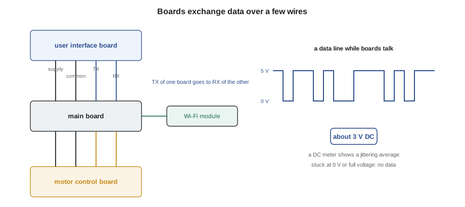
The boards must constantly share information. The user interface tells the main board which cycle the customer chose; the main board tells it what to display. The main board tells the motor board what speed to run; the motor board reports back the actual speed, any fault and sometimes the load it sensed. The Wi-Fi module reports status to the maker's cloud and passes remote commands in. All this travels over a few wires as digital data.
How boards talk
Most appliance boards use some form of serial communication, sending data one bit at a time on a single wire. A common arrangement uses four wires between two boards: a supply (often 5 V or 12 V DC, which may power the smaller board), a common, a transmit line (TX) and a receive line (RX). One board's TX connects to the other's RX, and the other way round. The data is a stream of short pulses between about 0 V and the logic voltage, at a fixed speed called the baud rate. Other designs share one data wire among several boards, use two wires twisted together for noise resistance, or pass data through an opto-isolator to keep a board isolated from line voltage (lesson 2). The protocols are the makers' own and are not documented for technicians; what matters in the field is whether the data is getting through.
Boards also send a regular heartbeat, a short message every fraction of a second that says "I am here." If one board stops hearing the other's heartbeat for a set time, it assumes the link is lost, stops the cycle for safety and shows a communication code. Some boards keep running on their own defaults, and the fault appears only in the history.
Worked problem
How much data a link carries
A link runs at 9,600 baud. Each byte takes about 10 bits on the line once the start and stop bits are included. How many bytes a second can it carry, and how long does a 20-byte message take?
Show solution
- Bytes per second:
- \[9{,}600 \div 10 = 960 \text{ bytes per second}\]
- Time for 20 bytes:
- \[\frac{20 \times 10}{9{,}600} \approx 0.021 \text{ s} \approx 21 \text{ ms}\]
Answer: About 960 bytes a second, and about 21 ms for a typical status message. A board can exchange several messages a second, which is why an interruption of even a fraction of a second, from a wire that opens as the tub shakes, can be enough to trip a communication fault.
What a communication fault looks like
Communication faults show up in several ways, depending on which link has failed and what the boards are designed to do.
- A communication fault code, such as the sample F60, shown on the display or stored in the history.
- A dead or frozen display while the main board still runs, or the reverse: a lit display that does not respond to keys, because the main board never receives them.
- A motor that does not start or stops partway, with a motor or inverter fault, because the motor board never received a speed command.
- An intermittent fault that clears when the power is switched off and on, and returns under vibration, heat or moisture.
- Faults that appear after a repair, when a connector was not fully seated, a harness was pinched behind a panel, or a replacement board was the wrong revision or was not configured (lesson 3).
The cause is rarely a failed microcontroller. In order of how often Dee finds them, the causes are: connectors not fully seated or with a terminal pushed back; harness damage from chafing, pinching, rodents or heat; water or detergent corrosion in a connector; a board that has lost its supply voltage because of a power supply or harness fault; a wrong or unconfigured replacement board; and only then a failed board.
Testing a communication link
The method works from the simplest checks to the least likely causes, with the tech sheet in hand.
- Read the fault history. Note which code, how often and in which part of the cycle. A fault only during spin points to vibration; only after a wash, to moisture; only on cold mornings, to a cracked solder joint or connector that opens as it contracts.
- Check the supply to each board. Many smaller boards are powered over the communication harness. Measure the supply pin to common at the smaller board's connector, connected, on DC volts. No supply means the board cannot talk at all.
- Look for data activity. With the boards powered and connected, a DC voltmeter on a data line shows an average voltage somewhere between 0 V and the logic voltage, which jitters as data flows. A line stuck at exactly 0 V or exactly the full logic voltage suggests no data is being sent on it. Some tech sheets give the expected average; some boards have an LED that flickers with data. This is a rough check, not a measurement of the data itself.
- Check the harness, power off. Unplug both ends, measure each wire end to end for continuity, then flex and press along the harness while watching the meter. Measure between wires, and from each wire to the cabinet, for unwanted connections.
- Inspect connectors. Look for terminals pushed back, bent pins, corrosion and burned spots, and check that each connector's latch and any secondary lock are engaged.
Worked problem
A wire that opens when it moves
Measured end to end with the harness still, a communication wire reads 0.3 Ω. When the harness is flexed where it crosses a bracket, the meter jumps to 1,400 Ω for a moment and then back. Another wire in the same harness reads 0.3 Ω steadily. What does this show?
Show solution
- A good wire of this length reads well under 1 Ω and stays steady.
- 0.3 Ω still is normal, but 1,400 Ω when flexed means the conductor is broken inside its insulation and touches only when still.
- The second wire is steady and good.
Answer: The first wire is broken at the flex point and opens intermittently, exactly the kind of fault that causes communication codes during spin. Repair or replace the harness and reroute it away from the bracket. A meter with a min/max or continuity beep function makes these brief opens easier to catch.
| What you find | What it suggests | Next step |
|---|---|---|
| No supply at the smaller board | Supply fault or broken supply wire | Check the supply at the main board and the harness |
| Supply present, data line stuck at 0 V or full logic voltage | One board is not transmitting, or the line is shorted or open | Check the harness; then the transmitting board |
| Data lines active at both ends, still a fault | Wrong or unconfigured board, or a board not responding | Check part numbers, revisions and configuration |
| Fault only under vibration | Harness chafe or loose connector | Flex test and inspect routing |
| Fault only after washes or defrosts | Moisture or corrosion in a connector | Inspect and repair the connector; fix the water source |
Working on communication harnesses safely
Communication harnesses look like low-voltage wiring, and usually they are. But on some appliances the main board's low-voltage side is non-isolated (lesson 2), and a harness running to a door display can then be at line potential relative to the cabinet. Unplug the appliance before unplugging or plugging any connector. Plugging a user interface board onto a live harness can damage both boards, because the pins do not all make contact at the same instant.
When a harness is damaged, the maker usually sells a replacement harness, and that is the preferred repair, because it restores the original routing, length and protection. Where the maker allows splicing, use the specified splice connectors and heat-shrink and keep twisted pairs twisted. Re-route and tie the harness exactly where the maker's diagram shows, away from brackets, hot surfaces and moving parts. A harness rerouted to save time is the most common reason the same fault comes back.
Electrical noise can also disturb data. Motor leads, heater leads and the inverter's output switch large currents very fast, and a data harness tied tightly alongside them can pick up interference. Makers route these harnesses separately and sometimes add ferrite cores; keep them where they were, and refit any ferrite that was removed.
After the repair
When the fault was a communication fault, the test after the repair must include whatever triggered it. Dee's washer had faulted only in spin, so after fitting the new harness she ran two full spin cycles, watched the display throughout, then cleared the fault history and noted in the work order that the history had been cleared after the test, so a future technician would know any new F60 was new. She also wrote down the routing problem, and the shop sent a note to the maker's field contact, because a harness tied too close to a bracket on the production line can affect many machines.
Ines added one more point. Some boards keep a communication error count separate from the fault history, visible only in the service mode. On a machine with an intermittent fault, watching that counter during a test cycle can show errors building up before they are bad enough to stop the machine. Where the tech sheet describes such a counter, use it before and after the repair.
Configuration and compatibility faults
Not every communication fault is a broken wire. Boards that talk to each other must also agree on what they are saying. A replacement user interface board of the wrong revision, a main board that has not been configured for the model, or a board with older firmware than its partner can all set a communication code or behave oddly, even with a perfect harness. Makers often design boards to check each other's identity at power-up; when they do not match, the display may show a configuration or compatibility code instead of the usual communication code.
This is why a communication fault after a board replacement sends the technician back to the parts system and the bulletins. Is the new board the current service part for this serial range? Did its instructions call for a configuration code, a software update or an adapter harness? Does a bulletin say both boards must be replaced together? On connected appliances, a pending firmware update on one board can occasionally leave the boards briefly out of step; finishing the update usually clears it (lesson 10).
Worked problem
How long before a lost link is reported
A main board expects a heartbeat from the user interface every 100 ms, and reports a communication fault after 30 missed heartbeats in a row. How long must the link be lost before the code is set?
Show solution
- \[30 \times 100 \text{ ms} = 3{,}000 \text{ ms} = 3 \text{ s}\]
Answer: About 3 seconds (sample timing). Shorter interruptions are tolerated, which is why an intermittent fault may show only in a communication error counter, or only when a wire is open for a few seconds at a time during a long spin.
Finally, remember that a communication fault can be the symptom of a board that has stopped working for another reason, such as a lost supply or a failed power supply. If the smaller board is completely dark, check its supply first. If it is lit but not responding, check the data lines, then the configuration, and only then the board.
Common mistakes
MistakeReplacing a board for a communication code.
InsteadCheck supplies, connectors and the harness first; boards are the least likely cause.
MistakeTesting a harness only while it is still.
InsteadFlex and press along it while watching the meter, to catch breaks that open with movement.
MistakePlugging a user interface board onto a live harness.
InsteadUnplug the appliance before connecting or disconnecting boards.
MistakeRerouting a repaired harness by a shorter path.
InsteadRoute and tie it as the maker's diagram shows, away from brackets, heat and motor leads.
MistakeClearing the fault history before testing.
InsteadTest through the cycle that caused the fault, then clear the history and note it.
Summary and key terms
- Appliances use several boards that exchange data over a few wires.
- A common link has supply, common, TX and RX; one board's TX goes to the other's RX.
- Boards send heartbeats and report a communication fault when they stop hearing each other.
- Communication faults show as codes, dead displays, motors that do not start and intermittent stops.
- Connectors and harnesses cause most communication faults; boards are the least likely cause.
- Check supplies, look for data activity, then test the harness with a flex test, power off.
- Unplug before handling connectors; some harnesses can be at line potential.
- Repair with the maker's harness, route it as designed, and test through the cycle that triggered the fault.
- Serial communication
- Sending data one bit at a time on a single wire.
- TX and RX
- Transmit and receive lines in a serial link.
- Baud rate
- The speed of a serial link in bits per second.
- Heartbeat
- A regular message one board sends to show it is still working.
- Communication fault
- A fault reported when boards stop exchanging data.
- Flex test
- Checking continuity while bending and pressing along a harness.
- Secondary lock
- An extra latch that holds a connector's terminals in place.
Practice problems
Work each problem on paper first, then reveal the answer to check.
Which line on one board connects to the TX line of the other?
Show answer
Its RX line.
A data line reads a steady 0 V with both boards powered. What does that suggest?
Show answer
No data is being sent, or the line is shorted or open.
Why do communication faults often appear only during spin?
Show answer
Vibration opens a damaged wire or loose connector.
What should be done before unplugging a user interface board?
Show answer
Unplug the appliance.
What must the test after a communication repair include?
Show answer
The part of the cycle that triggered the fault.
Lesson quiz · 5 questions
Score 60% or more to complete this lesson.
Create a free account to save your progress, take quizzes and earn a certificate.