
APP-320 · Lesson 5 of 12 · 28 min
Variable speed and inverter compressors
▶ Video coming soon A video version of this lesson is on the way.
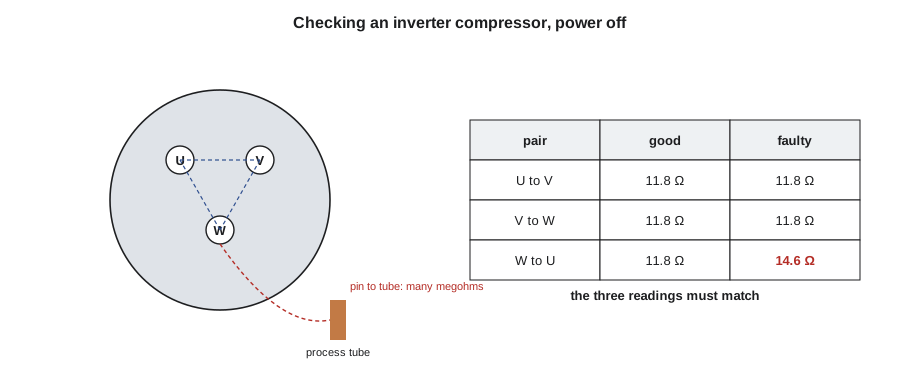
Dee's case file for Tuesday, September 1, was a refrigerator that sounded wrong. Barnaby Thistlewood in Minerva Park said his five-year-old French-door model had gone warm overnight, and that every few seconds it made a faint tick from the back. The fans ran and the display was normal. Dee pulled the refrigerator out, removed the rear cover and watched a small red light on the compressor's inverter board blink a pattern. With a clamp meter on the inverter's supply lead she saw what the tick was: a jump of about 4 A, then nothing, again and again, until after a dozen tries the board went quiet for several minutes. The inverter was trying to start the compressor and failing. With the refrigerator unplugged and the bus voltage measured at zero, she unplugged the three-wire compressor lead and measured the windings: 11.8 Ω, 11.8 Ω and 14.6 Ω. "An inverter compressor's three windings should match," she said. "One of these does not." The maker's sealed-system warranty covered the failure, and the maker approved a replacement refrigerator.
This lesson explains why refrigerators, freezers and air conditioners use variable-speed compressors, how an inverter drives a brushless compressor, what the main board and inverter board each do, how to test the system safely, and the mistakes that destroy inverter compressors and boards.
Why variable speed
A traditional household compressor is a single-speed machine with a single-phase induction motor, a start device and an overload, as the refrigerator course explained. It runs at full speed until the thermostat or board is satisfied, then stops, then starts again when the compartment warms. Each start draws a surge of current and wastes some energy, and the compartment temperature swings up and down between starts.
A variable-speed compressor, often called an inverter compressor or linear-speed compressor, can run anywhere within a speed range, typically from about 1,600 to 4,500 rpm (typical). After a door has been left open or warm food loaded, it runs fast to pull the temperature down. Most of the time it runs slowly and for long periods, which keeps the temperature steadier, runs more quietly and uses less energy, because a compressor working gently on a well-matched load is more efficient than one cycling hard. Room air conditioners and heat pump dryers and water heaters use the same idea. Some refrigerators use a linear compressor, in which a piston is driven back and forth directly by a linear motor; it is also driven by an inverter-type board and tested by the maker's procedure.
Worked problem
What variable speed can save
A sample single-speed refrigerator uses about 520 kWh a year. A similar model with an inverter compressor uses about 420 kWh a year (sample figures; actual ratings are on each model's energy label). How much energy does the inverter model save, as a fraction, and what is that worth at a sample electricity price of 0.12 dollars per kWh?
Show solution
- Energy saved:
- \[520 - 420 = 100 \text{ kWh a year}\]
- Fraction saved:
- \[100 \div 520 \approx 0.19, \text{ about 19 in 100}\]
- Value:
- \[100 \times 0.12 = 12 \text{ dollars a year}\]
Answer: About 100 kWh a year, roughly a fifth, worth about 12 dollars a year at the sample price. The savings and the steadier temperatures are why most new refrigerators use variable-speed compressors.
How an inverter drives the compressor
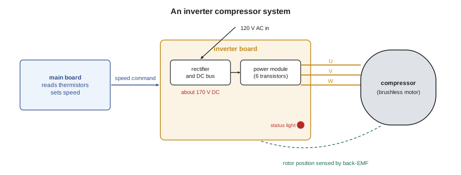
An inverter compressor's motor is a brushless DC (BLDC) motor, also called a permanent-magnet synchronous motor. Its rotor carries permanent magnets and has no windings, brushes or start device. Its stator has three windings, connected in a star or delta inside the shell, and brought out to three pins, often labeled U, V and W. Because a three-winding motor needs three-phase power, and a house has only single-phase, a separate inverter board makes it.
The inverter board does this in three steps. It rectifies the household supply and charges a DC bus capacitor, to about 170 V DC from a 120 V supply on most North American refrigerators, or higher on boards with a voltage doubler (lesson 2). Six power transistors, usually built into a single intelligent power module (IPM), then switch the bus voltage onto the three windings in turn, many thousands of times a second, building up a rotating magnetic field. The frequency of that field sets the motor's speed, and the switching pattern sets the effective voltage. Finally, the board senses where the rotor is, usually by measuring the voltage that the spinning magnets induce in the unpowered winding (called back-EMF), so it can keep the field just ahead of the rotor. Because the rotor's position can only be sensed once it is turning, the board starts the motor with a special sequence, and if the motor does not follow, it stops and tries again.
Worked problem
Frequency and compressor speed
A compressor motor has four poles (two pole pairs). Its speed in rpm equals 60 times the frequency divided by the number of pole pairs. What speeds does it run at 50 Hz, 100 Hz and 150 Hz?
Show solution
- At 50 Hz:
- \[\frac{60 \times 50}{2} = 1{,}500 \text{ rpm}\]
- At 100 Hz:
- \[\frac{60 \times 100}{2} = 3{,}000 \text{ rpm}\]
- At 150 Hz:
- \[\frac{60 \times 150}{2} = 4{,}500 \text{ rpm}\]
Answer: The inverter changes the speed by changing the frequency: 1,500, 3,000 and 4,500 rpm. That is why an ordinary meter on the compressor leads shows readings that change with speed and cannot be compared with a fixed value; the output is not a plain 50 or 60 Hz supply.
Who decides what
The main board decides how much cooling is needed. It reads the thermistors, the door switches and the user settings and sends the inverter board a speed command. The command may be a pulse-width-modulated signal whose duty cycle or frequency sets the speed, a simple DC voltage, or a digital message on a serial line (lesson 7). The tech sheet says which, and gives the expected values. The inverter board decides how to run the motor at that speed: it starts the compressor, holds the speed, and protects the compressor and itself. It stops the compressor and flags a fault if it sees excessive current, a locked rotor, an overheated module, a bus voltage too high or too low, or lost communication.
This split is the key to diagnosis. If the compressor does not run, the technician must find out whether the main board is asking it to run, whether the inverter board is receiving power and the command, and whether the inverter is trying to start the compressor. Many inverter boards have a status light that blinks a pattern for each fault; the tech sheet decodes it. Many main boards show the compressor speed command and the inverter's fault in the service mode.
Testing an inverter compressor system
Dee's sequence, adapted from the makers' procedures, runs from the outside in. Every step is done with the cover and the procedure for that model.
- Confirm the complaint and the command. Check the compartment temperatures, then use the service mode to force the compressor on or read the speed command. If the main board is not asking for the compressor, the problem is upstream: sensors, settings or the main board.
- Check the inverter board's supply. With everything connected, measure 120 V AC at the inverter board's input (typical). No supply means a harness, connector, fuse or main board relay problem.
- Check the command signal. Measure the speed command at the inverter's connector as the tech sheet describes. A pulse-width signal read on a DC voltmeter shows an average that wanders; the tech sheet says what range to expect, and some makers say to measure frequency instead.
- Watch the start attempts. A clamp meter on the inverter's supply lead shows whether the inverter is trying. No current at all means the inverter is not attempting a start. A short spike that drops off and repeats means it is trying and the compressor is not following. A steady current means it is running.
- Check the windings, power off. Unplug the refrigerator, measure the bus voltage until it is near zero, unplug the compressor lead, and measure the resistance between each pair of pins: U to V, V to W and W to U. The three readings should be equal, typically within a fraction of an ohm. Then measure each pin to the copper process tube or a clean spot on the shell: the reading should be very high, typically many megohms.
Worked problem
Spotting an unbalanced winding
Dee read 11.8 Ω, 11.8 Ω and 14.6 Ω between the three pairs of pins. How far is the odd reading from the others, as a fraction?
Show solution
- \[\frac{14.6 - 11.8}{11.8} \approx 0.24\]
- About 24 in 100 higher than the other two readings.
Answer: A difference of about a quarter is far outside what a healthy three-winding motor shows; matching readings within a fraction of an ohm are normal. The compressor has an internal winding fault. Matching readings do not prove the compressor is good, though: a compressor can be mechanically seized or have a valve fault with perfect windings, which is why the start attempts and the current matter too.
The tech sheet gives the actual winding value for each compressor. Readings that are equal but far from the specification, or a low reading to the shell, also condemn the compressor. Some makers provide a compressor tester or a test mode on the inverter board that runs the compressor at a fixed speed for checking; where they do, use it.
What never to do
Two mistakes destroy inverter compressors and boards. First, never connect an inverter compressor directly to the household supply with a test cord, the way an old single-speed compressor might be tested. A BLDC compressor has no start winding and is not designed for a single-phase 60 Hz supply; applying it can burn the windings or demagnetize the rotor at once. Second, never unplug or plug the compressor lead with the inverter board powered, and never probe the inverter's output pins while it is running unless the maker's procedure says how. The output can be well over 100 V and switches very fast, and an arc at the connector can destroy the power module.
The DC bus deserves the same respect as in lesson 2. An inverter board may hold its bus voltage for a minute or more after the refrigerator is unplugged. Measure it at the test points the tech sheet names before touching the board or its connectors. Inverter boards often sit low on the back of the cabinet, close to the floor and the condenser fan; check for dust, water from the drain pan and signs of rodents, all of which cause board failures.
When the inverter board itself has failed, the replacement is usually straightforward: the maker's procedure lists the connectors, any configuration and a final test. But a board that failed because the compressor was shorted or locked will fail again on the same compressor. Dee checks the windings and the shell reading before every inverter board replacement, and records them on the work order.
Inverter systems in other appliances
The same inverter principles appear in other appliances, and the testing method carries over. Room and window air conditioners with inverter compressors, which the next course covers, use an inverter board on the outdoor side of the unit, often with a larger DC bus because they run on 230 V or 240 V. Heat pump dryers and heat pump water heaters use small inverter or fixed-speed compressors with the same cautions about the bus and about never applying line voltage straight to the compressor. Dishwashers and washers use inverter boards for their wash pumps and drive motors (lesson 6), and induction cooktops use the same kind of power stage to drive their coils at 20 to 100 kHz (typical), as the cooking course explained.
Some refrigerators combine the main and inverter boards into one, mounted at the back near the compressor, so there is no separate speed command to measure; the service mode then shows the commanded and actual speed, and the tech sheet gives a test that runs the compressor at a fixed speed. Others put the inverter inside a sealed box on the compressor's terminal cluster. Whatever the layout, the questions are the same: is the control asking for cooling, is the inverter powered and commanded, is it trying to start the compressor, and are the compressor's windings and insulation sound?
Sealed-system faults can also look like inverter faults. A compressor that runs but cannot pump because of a leak, a restriction or a failed valve will run at high speed for long periods, and some controls then flag a fault because the temperature never falls as expected. The refrigerator course explained how to judge these by wattage, frost patterns and temperatures; on inverter refrigerators, remember that the compressor's power changes with speed, so compare readings with the tech sheet's values at the speed shown in the service mode, not with a fixed figure.
Worked problem
Power at different compressor speeds
A tech sheet gives an inverter compressor's typical input power as about 45 W at its lowest speed and about 150 W at its highest (sample values). A clamp meter on the refrigerator's supply cord reads 1.3 A at 120 V with the compressor at full speed and the fans running. Ignoring power factor, is the compressor plausibly running at full speed?
Show solution
- Apparent power on the cord:
- \[120 \times 1.3 = 156 \text{ W}\]
- Subtract roughly 10 W for fans and the board (sample):
- \[156 - 10 \approx 146 \text{ W}\]
Answer: About 146 W, close to the 150 W expected at full speed, so the compressor is plausibly at full speed. The same reading at the lowest commanded speed would be far too high and worth investigating. (A meter that reads true watts gives a better comparison than amps times volts.)
Common mistakes
MistakeTesting an inverter compressor with a direct-start test cord.
InsteadNever; use the inverter, the maker's test mode or a maker-approved tester.
MistakeComparing the compressor lead voltage with a fixed value.
InsteadThe inverter's output changes in frequency and voltage with speed; follow the tech sheet's method.
MistakeReplacing an inverter board without checking the windings.
InsteadCheck that the three readings match and that the shell reading is very high first.
MistakeAssuming matching windings prove the compressor is good.
InsteadA compressor can still be seized or have a valve fault; check the start attempts and current.
MistakeUnplugging the compressor lead with power on.
InsteadUnplug the appliance, measure the bus voltage near zero, then disconnect.
Summary and key terms
- Variable-speed compressors run slowly for long periods, saving energy and holding steadier temperatures.
- An inverter compressor is a brushless motor with three windings and permanent magnets.
- The inverter board rectifies the supply to a DC bus and switches it onto the windings at a variable frequency.
- The main board sets the speed command; the inverter board starts, runs and protects the compressor.
- Test from the outside in: command, inverter supply, command signal, start attempts, then windings.
- The three windings should read equal, with a very high reading to the shell.
- Never connect an inverter compressor directly to line voltage.
- Check the compressor before replacing an inverter board, and respect the DC bus.
- Inverter compressor
- A variable-speed compressor driven by an inverter board.
- Brushless DC motor
- A motor with a permanent-magnet rotor and electronically switched stator windings.
- Inverter board
- The board that makes variable-frequency power for a compressor or motor.
- Intelligent power module
- A single package holding the six switching transistors of an inverter.
- Back-EMF
- The voltage a spinning permanent-magnet rotor induces in a winding.
- Speed command
- The signal from the main board that tells the inverter how fast to run.
- Status light
- An LED on an inverter board that blinks a fault pattern.
Practice problems
Work each problem on paper first, then reveal the answer to check.
What sets an inverter compressor's speed?
Show answer
The frequency of the power the inverter feeds to the windings.
What should the three winding readings of an inverter compressor show?
Show answer
They should be equal, within a fraction of an ohm.
A clamp meter shows repeated short current spikes at the inverter input. What does that mean?
Show answer
The inverter is trying to start the compressor, and the compressor is not following.
Why must an inverter compressor never be started directly on line voltage?
Show answer
It is not designed for it and can be destroyed at once.
What must be checked before replacing a failed inverter board?
Show answer
The compressor's windings and its insulation to the shell.
Lesson quiz · 5 questions
Score 60% or more to complete this lesson.
Create a free account to save your progress, take quizzes and earn a certificate.