
APP-120 · Lesson 3 of 12 · 22 min
Reading ladder diagrams and wiring schematics
▶ Video coming soon A video version of this lesson is on the way.
After a coffee break on the same Thursday night, October 29, Dee unfolded a tech sheet she had taken from inside the back panel of a scrapped electric dryer. "This is the most valuable piece of paper in the machine," she said. "It tells you every wire, every part and every path. Most technicians who struggle with electrical faults struggle because they can't read this sheet." She gave Kiran a highlighter, and for the next hour they traced every circuit on it. He took a copy home and spent the weekend tracing it again.
APP-110 showed where to find service information and introduced the two kinds of drawing in it. This lesson teaches how to read them properly: the symbols, the ladder layout, wire colors and connector labels, the state in which parts are drawn, and a step-by-step way to trace a path from the supply to a load and back. The sample diagrams in this lesson are drawn for training and do not belong to any manufacturer, but they follow the conventions found on real tech sheets.
Two kinds of drawing
A wiring diagram, sometimes called a pictorial or connection diagram, shows the parts roughly where they sit in the appliance, with every wire drawn from terminal to terminal and labeled with its color. It is good for finding a part and a wire in the cabinet, but the crossing wires make it hard to follow how the circuit works.
A schematic, usually drawn as a ladder diagram, shows how the circuit works rather than where the parts are. The supply runs down two vertical rails, and each load and the switches that control it are drawn on a horizontal rung between the rails. A technician reads the schematic to understand the circuit and decide what to test, then uses the wiring diagram, or the wire colors and connector labels, to find the test points in the cabinet.
Symbols
Schematic symbols are largely standard, though each manufacturer has small variations, and every tech sheet has a key. The most common are shown in the figure. A few points cause most of the confusion. A switch contact drawn open is a normally open (NO) contact, which closes when its switch or relay is operated; a contact drawn closed is normally closed (NC). A thermostat symbol usually shows its rating, such as an opening temperature. A relay is drawn in two parts: its coil, often on a different rung or even a different page from its contacts, and its contacts, labeled with the same name or number as the coil.
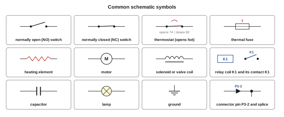
Parts are drawn at rest
The single most important rule for reading a schematic is that every switch and contact is drawn in its resting position, usually with the appliance unplugged, the door open or closed as the key states, and the timer or control in the off position. A door switch drawn open on a dryer schematic is open with the door open; it closes when the door is shut. A cycling thermostat drawn closed is closed when the dryer is cool. A relay contact drawn open is open until the control board energizes its coil.
This means that a schematic shows the circuit before anything happens. To understand how a load gets power, you must mentally operate the switches: close the door switch, turn the timer to the cycle, press start, and see which contacts change. Many tech sheets help with a timer or cycle chart, a table showing which contacts are closed at each step of a cycle.
The ladder layout
In a 120 V appliance ladder diagram, the left rail is usually the hot conductor, often labeled L1, and the right rail is the neutral, labeled N. In a 120/240 V appliance such as a dryer or range, there are three rails: L1, L2 and N. Loads that need 240 V are drawn on rungs between L1 and L2, and loads that need 120 V are drawn on rungs between L1 or L2 and N. The ground is usually shown as a symbol connected to the cabinet or as a separate line.
Each rung reads like a sentence from left to right: power comes from the rail, passes through the switches and protective devices in series, reaches the load, and returns to the other rail. If every switch on a rung is closed, the load on that rung has voltage. The rungs are in parallel with each other, which is exactly the combination circuit of lesson 2.
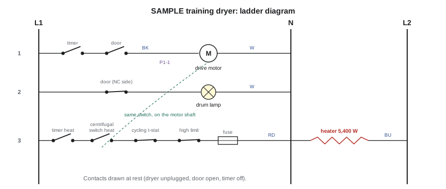
On the sample dryer, notice something that is easy to miss: the heater rung includes a contact on the drive motor's centrifugal switch. That contact closes only when the motor is up to speed. So the heater cannot come on unless the motor is running, which stops the heater from cooking the clothes in a still drum. A dryer that tumbles but does not heat could have a fault in the heater rung itself or in the motor's centrifugal switch contact, which lives on a different part. Without the schematic, a technician might never look at the motor for a no-heat fault.
Wire colors and connector labels
Tech sheets label wires by color, usually with two-letter abbreviations such as BK for black, W or WH for white, R or RD for red, BU or BL for blue, OR for orange, Y or YL for yellow, GN for green, GY for gray, PK for pink, V for violet and BR or BN for brown. A wire with a tracer stripe is shown with both colors, such as W-R for white with a red stripe, or W/R. Learn the abbreviations from the key, because they vary.
Connectors are labeled by name and pin. P3-2 might mean pin 2 of connector P3 on the control board. Many boards print their connector names on the board itself, so a technician can find P3 and count to pin 2. Wire colors plus connector pins let a technician find the exact test point in the cabinet that matches a point on the schematic.
| Label | Meaning | Example |
|---|---|---|
| BK, RD, BU | Wire colors: black, red, blue | BK from L1 to the door switch |
| W-R or W/R | White wire with a red tracer stripe | Neutral return from the motor |
| P3-2 | Connector P3, pin 2 | Control board output to the inlet valve |
| NO, NC, COM | Normally open, normally closed and common terminals of a switch or relay | Door switch COM and NO |
| K1, RY2 | Relay names; the coil and its contacts carry the same name | K1 coil on the board, K1 contact on the heater rung |
Tracing a path, step by step
Dee taught Kiran a method that works on any schematic. Use a highlighter or a finger, and say each step out loud.
- Start with the complaint. Name the load that is not working, such as the heater, the drain pump or the inlet valve.
- Find the load on the schematic and identify its rung.
- Trace from the load back to one supply rail, listing every switch, contact, protective device and connector pin on the way.
- Trace from the load to the other rail, listing everything on that side too. Many technicians trace only one side and miss a fault on the return.
- For each switch and contact in the path, decide what has to happen for it to close: door shut, timer on heat, relay energized, motor up to speed, temperature below the opening point.
- Write the path as a list of test points, from rail to load to rail, with the wire color or connector pin at each.
- Only then pick up the meter, and test the points in an order that splits the path in half, as lesson 12 shows.
Worked problem
Listing the heater path on the sample dryer
Using the sample dryer ladder, list the parts in the heater path from L1 to L2 and what must happen for each to close.
Show solution
- From L1: timer heat contact, closes when the timer is set to a heat cycle.
- Centrifugal switch heat contact, closes when the drive motor is up to speed.
- Cycling thermostat, closed while the exhaust air is below its opening temperature.
- High-limit thermostat, closed unless the heater housing overheats.
- Thermal fuse, closed unless it has blown.
- Heater, then back to L2.
Answer: Six items, five of them switches or protectors. For the heater to work, the timer must be on heat, the motor running, both thermostats cool enough and the fuse intact. Each item is a test point, and each is in series, so the method of lesson 2 applies: with the dryer running on heat, the open item has the full 240 V across it.
Reading the timer or cycle chart
Electromechanical timers, still found on many dryers and older washers and dishwashers, close different sets of contacts as their cam turns through the cycle. The cycle chart on the tech sheet is a grid: the columns are the timer increments or cycle steps, and the rows are the contacts, with a bar or mark showing when each is closed. To test a load, set the timer to a step where the chart shows its contact closed. Testing a fill valve with the timer on a drain step will always show no voltage, and that is not a fault.
Electronic controls replace the cam with relays and switches on a board, controlled by software. Their schematics show the board as a box with numbered connector pins, and the board's outputs as relay contacts or simply as pins with a voltage when active. Lesson 9 covers relays, and APP-320 covers control boards, service modes and fault codes in depth. Even with an electronic board, the loads, switches and protective devices outside the board follow the same ladder logic.
Low-voltage and DC circuits on the same sheet
Modern schematics often show two kinds of circuit on one sheet. The line-voltage circuits, at 120 V or 240 V AC, feed the heaters, motors, valves and lamps. The low-voltage circuits, often 5 V or 12 V DC from a power supply on the board, feed sensors, switches that report to the board, and the coils of the board's relays. The two are usually drawn in different areas or with different line styles, and the tech sheet notes the voltages. Never apply line voltage to a low-voltage terminal or a sensor input, and do not assume that a pin on a board connector is safe to touch: a board connector can carry line voltage on one pin and 5 V DC on the next.
When the drawing and the appliance disagree
Sometimes the wire colors in the cabinet do not match the sheet. The appliance may be a different revision, a part may have been replaced with a different harness, or a previous repair may have changed the wiring. Check the model and serial number against the sheet, look for a revision letter, and if the difference is real, trust what you can trace and measure in the cabinet, and write it on the work order. Never assume a wire is what the sheet says it is without checking where it goes.
Kiran found one such difference on the scrapped dryer. The sheet showed a blue wire from the thermal fuse to the heater; the dryer had a red one, with a splice halfway along. Dee looked at it and shrugged: "Somebody's repair. Probably fine, but now you know where the splice is if you ever get a no-heat on this model."
Keeping the tech sheet useful
Penfold's technicians photograph the tech sheet on every call before they start, so that the drawing is on their phone if the paper copy is greasy, torn or missing. When a sheet is missing, the manufacturer's service site or the parts distributor can usually supply it from the model number. Dee also keeps a binder of annotated sheets for the models Penfold sees most, with test values and common faults written in the margins.
Common mistakes
MistakeReading a schematic as if the switches were in their working positions.
InsteadParts are drawn at rest; mentally operate each switch and relay to see when a load gets power.
MistakeTracing only from the hot rail to the load.
InsteadTrace both sides, back to both rails; faults on the return side are common.
MistakeTesting a timer-controlled load at a step where its contact is open.
InsteadUse the cycle chart to set the timer to a step where the load should be on.
MistakeIgnoring a contact that sits on another part, such as the motor's centrifugal switch.
InsteadList every item on the rung, wherever it is in the cabinet.
MistakeAssuming every pin on a control board connector is low voltage.
InsteadBoard connectors can mix line voltage and low-voltage DC; check the sheet.
MistakeTrusting the sheet over the cabinet when the wiring differs.
InsteadCheck the revision and model, trace what is really there, and record the difference.
Summary and key terms
- A wiring diagram shows where parts and wires are; a ladder schematic shows how the circuit works.
- Switches and contacts are drawn at rest; mentally operate them to see when a load gets power.
- Rails are L1 and N, or L1, L2 and N; each rung is a series path, and the rungs are in parallel.
- Wire colors and connector pins link the schematic to test points in the cabinet.
- Trace from the load back to both rails, list every switch and protector, and note what closes each.
- Use the timer or cycle chart to set up the step at which a load should be on.
- Schematics may mix line-voltage and low-voltage DC circuits; treat every pin with care.
- Wiring diagram
- A drawing that shows the parts and wires roughly where they are in the appliance.
- Schematic
- A drawing that shows how a circuit works, without regard to where the parts are.
- Ladder diagram
- A schematic with supply rails down the sides and each load on a horizontal rung.
- Rung
- One horizontal path on a ladder diagram, from one rail through switches and a load to the other rail.
- Normally open (NO)
- A contact that is open at rest and closes when operated.
- Normally closed (NC)
- A contact that is closed at rest and opens when operated.
- Cycle chart
- A table on the tech sheet showing which timer or relay contacts are closed at each step of a cycle.
- Tracer
- A colored stripe on a wire's insulation, shown on schematics with a second color.
Practice problems
Work each problem on paper first, then reveal the answer to check.
On a schematic, is a door switch drawn with the door open or closed?
Show answer
In its resting position, which the tech sheet key states; usually with the door open.
What does P3-2 usually mean?
Show answer
Pin 2 of connector P3.
Why does a dryer heater rung often include a contact on the drive motor?
Show answer
So that the heater can only come on when the motor is running.
Which side of the load should you trace?
Show answer
Both sides, back to both supply rails.
Why use the cycle chart before testing a timer-controlled load?
Show answer
To set the timer to a step where that load's contact is closed.
Lesson quiz · 5 questions
Score 60% or more to complete this lesson.
Create a free account to save your progress, take quizzes and earn a certificate.