
APP-120 · Lesson 11 of 12 · 25 min
Testing components with power off and on
▶ Video coming soon A video version of this lesson is on the way.
On Monday evening, November 9, after a long day preparing old appliances for the recycler, Dee kept Kiran at the shop for an extra hour at her test board. She had hidden three faults in it: an open wire, a switch with burned contacts and a disconnected neutral. "Each of these fools a different test," she said. "The open wire is easy with the power off. The burned switch passes with the power off and fails with the power on. And the open neutral will show you a voltage that isn't really there. If you only know one way of testing, one of these three will beat you."
Every component can be tested with power off, by measuring resistance, and with power on, by measuring voltage and current while it works. Each kind of test finds faults the other misses. This lesson explains when to use each, how to do them safely, how to read voltage across parts in a working circuit, how to avoid being fooled by ghost voltages and meter loading, and why a voltage drop under load is the most powerful test a technician has.
Power-off tests
Power-off tests are the safest and should usually come first. With the appliance unplugged or its breaker off and locked out, and capacitors discharged, a technician can measure the resistance of elements, windings, coils, sensors and wiring, check switches for continuity in each position, and check for shorts to the cabinet. The rules from APP-110 still apply: prove the supply is dead with the live-dead-live check, isolate the part by disconnecting at least one lead so parallel paths do not change the reading, and compare with the tech sheet.
Power-off tests find opens and shorts reliably. They do not find faults that appear only under load or at temperature, and they cannot show whether a part is getting the voltage it needs. A switch with burned contacts may read 0.2 Ω on an ohmmeter, which passes only a tiny current, and still fail when it carries 13 A. A thermostat may read closed at room temperature and open early when it warms. A sensor may read correctly cold and drift hot.
Power-on tests
Power-on tests show what is really happening while the appliance runs. They are live tests, done only when needed, with the precautions from APP-110: shrouded probes on a properly rated meter, one hand where possible, clips set up with the power off, no jewelry, dry hands and floor, and attention to moving parts, heat and water. Live work on household appliances is still live electrical work, and the safe-work practices of NFPA 70E and the employer's procedures apply.
Three power-on measurements answer most questions. Voltage at the supply tells whether the appliance is being fed correctly. Voltage across the load, when it should be on, tells whether the controls are delivering power to it. Current through the load tells whether it is drawing what it should. A fourth, voltage across a closed switch or connection, finds hidden resistance, and the rest of this lesson builds up to it.
Reading voltage across parts
Lesson 2 showed that, in a series circuit carrying current, a good closed switch or connection has almost no voltage across it, and the load has almost all of it. In a series circuit with no current, because something is open, the open part has the full supply across it and everything else has none. Those two facts give a simple map of what a voltage reading across a part means.
| Circuit state | Voltage across a good closed switch | Voltage across the load | Voltage across an open part |
|---|---|---|---|
| Working, current flowing | Close to 0 V (a few tenths at most) | Close to full supply | No open part |
| Open somewhere, no current | 0 V | 0 V | Full supply |
| High resistance in a connection or contact | Several volts across the bad point | Less than the supply | Not open; current still flows, but less |
Voltage drop: the test that finds hidden resistance
A connection or contact with high resistance is a fault that power-off tests miss and that causes some of the most frustrating calls: elements that heat slowly, motors that run weak, and terminals that burn again after being replaced. With current flowing, the bad point has voltage across it, which is the voltage drop. Measuring across each switch, terminal and connector in a working path finds it.
Worked problem
A burned terminal in series with an element
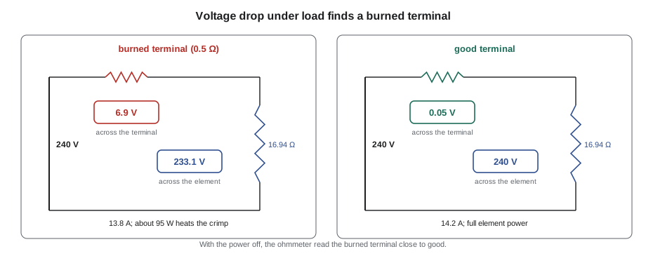
An oven's bake element measures 16.94 Ω, rated 3,400 W at 240 V. Its wire terminal has burned and has a resistance of about 0.5 Ω, which reads close to good on an ohmmeter. With 240 V across the element and terminal together, what current flows, what voltage drops across the terminal, and what power is turned into heat at the terminal?
Show solution
- Total resistance: 16.94 + 0.5 = 17.44 Ω.
- \[I = \frac{240}{17.44} = 13.76\ \text{A}\]
- Voltage drop across the terminal: 13.76 × 0.5 = 6.88 V.
- \[P_{terminal} = I^2 R = 13.76^2 \times 0.5 = 94.7\ \text{W}\]
Answer: About 13.8 A flows, about 6.9 V drops across the terminal, and about 95 W of heat is made right at that small connection: as much as a bright incandescent lamp, concentrated in a crimp. A good connection carrying the same current drops well under 0.1 V. That is why burned terminals keep burning, and why measuring the voltage drop across each connection under load finds them when an ohmmeter will not.
Dee's burned-switch fault on the board showed the same thing. With the power off, the switch read 0.3 Ω, a pass. With the element on and drawing about 8 A through it, the meter across the switch read 4.1 V. A good switch at that current reads a small fraction of a volt. The switch had burned contacts and would have failed completely within weeks.
Ghost voltages and meter loading
Most digital multimeters have a very high input resistance, often 10 MΩ, so that they barely affect the circuit they measure. That has a side effect. A wire that is disconnected at one end but runs alongside live wires in a harness can pick up a voltage through capacitive coupling, and a high-resistance meter reads it, sometimes 50 V or more, even though the wire cannot supply any real current. This is a ghost or phantom voltage.
Dee's hidden open neutral did exactly that. With the neutral disconnected at one end, the meter read 74 V from the lamp's neutral terminal to ground. Kiran first thought the neutral was carrying current. Then Dee had him switch his meter to its low-impedance setting, often marked LoZ, which puts a much lower resistance across the leads and drains any coupled voltage. The reading fell to under 1 V: the neutral was simply open and floating. Many meters for electrical work have a LoZ or similar function; where yours does not, confirm a doubtful reading by measuring the load's current, or by measuring to a known good conductor.
Worked problem
Is it real voltage?
With a lamp switched off at a switch that opens its hot, a technician measures 46 V from the lamp's hot terminal to neutral on a 10 MΩ meter. On the meter's LoZ setting, the reading falls to 0.6 V. Is the lamp terminal live?
Show solution
- A real supply would hold its voltage when the LoZ load is applied.
- The reading collapses under the low-impedance load, so the 46 V was coupled, not supplied.
Answer: No. The terminal is not connected to the supply; the 46 V was a ghost voltage picked up from nearby live wires. It still deserves respect: treat any wire as live until proven otherwise, and always prove dead with the live-dead-live check before touching.
Back-probing and test points
On many appliances, especially those with control boards, the test points are the pins of a connector. Back-probing means sliding a thin probe tip into the back of the connector, alongside the wire, until it touches the terminal, without unplugging the connector, so the circuit keeps working while you measure. Use thin back-probe pins made for the purpose, never force a probe into the front of a connector socket, which can spread the terminal and cause a new loose connection, and never pierce wire insulation with a probe. Check the tech sheet for which pins carry line voltage and which carry low-voltage DC before probing.
Some appliances have test points built in, such as a dryer's terminal block, a board's labeled test pads, or a range's terminal strip. Many control boards also have a service or diagnostic mode, which lets a technician turn each output on in turn, read sensor values and see fault history. APP-320 covers service modes in depth; for now the point is that a service mode makes power-on tests safer and faster, because the technician chooses which load is on.
Jumpers and bypasses
A jumper wire across a switch or contact is an old test: if the load starts when the switch is jumped, the switch was open. It is also dangerous if misused, because the switch may be a safety device. Penfold's rules, which match good practice across the trade, are strict. Jump a part only to confirm a diagnosis already made by measurement; never jump a thermal fuse, high limit, door interlock or overload with the appliance unattended or running normally; use an insulated jumper with clips, set up with the power off; remove it before leaving; and never jump anything on a control board. In almost every case, a voltage measurement across the part gives the same answer without the risk.
Choosing the test
Dee summed up the month's teaching on choosing tests in four sentences that Kiran wrote inside the cover of his notebook. Use power off to find opens, shorts and grounds. Use power on to see whether a load is getting voltage and drawing current. Use voltage drop under load to find bad connections and burned contacts. Use LoZ or a current reading to tell real voltage from ghost voltage.
| Fault | Best found with power off | Best found with power on |
|---|---|---|
| Open element, winding or coil | Yes: OL resistance | Also: voltage present, no current |
| Short to the cabinet | Yes: reading to the cabinet | Trips breaker or GFCI |
| Burned contact or connection | Often missed: reads near good | Yes: voltage drop under load |
| Missing supply or control output | Not possible | Yes: no voltage at the load |
| Part failing only when hot | Missed when cold | Yes: test at operating temperature |
| Floating, open neutral | Yes: OL end to end | Can show ghost voltage; use LoZ |
Worked problem
Working out the order of tests
A dryer runs but does not heat. The schematic shows the heater rung from lesson 3: timer heat contact, centrifugal switch heat contact, cycling thermostat, high limit, thermal fuse and heater. In what order should Kiran test?
Show solution
- First, power on: measure the supply, L1 to L2 at the terminal block, about 240 V.
- Still powered, with the dryer running on a heat cycle: measure across the heater. If 240 V is present, the heater should be heating; clamp its lead. No current with voltage present means the heater is open.
- If there is no voltage across the heater, measure across each switch and protector in the rung; the open one has the full 240 V across it.
- Power off: confirm the open part by resistance, and find why it opened before replacing it.
Answer: Supply, then the load, then the series parts, then confirm with power off. Measuring across the heater first splits the circuit in two: it tells at once whether the fault is the heater or something before it. Lesson 12 builds that split into a full method.
Recording readings as you go
Dee insisted that Kiran write every reading on the work order as he took it, with the test points named, such as "across element T1 to T2, bake on: 232 V". Written readings stop a technician from going round in circles, let a second technician pick up the job, and give the before and after evidence that a repair worked. They also protect the company if a customer later questions the diagnosis.
Common mistakes
MistakePassing a switch that reads close to 0 Ω on the ohmmeter.
InsteadBurned contacts can pass an ohmmeter test; measure the voltage drop across them under load.
MistakeTrusting a voltage reading on a disconnected wire.
InsteadHigh-impedance meters read ghost voltages; check on LoZ or with a current reading.
MistakeForcing probes into the front of connector sockets.
InsteadBack-probe with thin pins, or measure at a terminal; a spread socket becomes a new loose connection.
MistakeJumping a thermal fuse to see if the dryer heats.
InsteadMeasure across it instead; never leave a safety device bypassed.
MistakeDoing live tests without setting up first.
InsteadFit clamps, back-probe pins and test leads with the power off, then power on.
MistakeSkipping power-on tests to save time.
InsteadA missing supply or control output can only be found with the power on.
Summary and key terms
- Power-off tests find opens, shorts and grounds safely; they miss faults that appear only under load or heat.
- Power-on tests show whether a load gets voltage and draws current; follow live-work precautions.
- In a working series path, good closed parts drop almost no voltage; an open part has the full supply across it.
- Voltage drop under load finds burned contacts and connections that pass an ohmmeter test.
- High-impedance meters can read ghost voltages; LoZ mode or a current reading tells real from coupled voltage.
- Back-probe connectors with proper pins and check which pins carry line voltage.
- Jumpers only confirm a diagnosis; never bypass safety devices or jump board circuits.
- Power-off test
- A resistance or continuity test with the appliance de-energized.
- Power-on test
- A voltage or current measurement while the appliance is energized and working.
- Voltage drop
- The voltage across a part or connection while current flows through it.
- Ghost voltage
- A voltage read on a disconnected conductor because of coupling from nearby live wires.
- LoZ
- A low-impedance meter setting that drains ghost voltages.
- Back-probing
- Measuring at a connector terminal from behind, alongside the wire, without disconnecting it.
- Jumper
- A wire used briefly to bypass a switch or contact during a controlled test.
Practice problems
Work each problem on paper first, then reveal the answer to check.
A switch reads 0.3 Ω with power off and 4.1 V across it while carrying 8 A. Is it good?
Show answer
No; it has burned contacts with high resistance under load.
What voltage drops across a 0.5 Ω connection carrying 13.76 A?
Show answer
About 6.9 V.
A disconnected wire reads 74 V on a 10 MΩ meter and 0.8 V on LoZ. What does that show?
Show answer
It was a ghost voltage; the wire is not connected to a supply.
Why should the voltage across the load be measured early on a no-heat dryer?
Show answer
It splits the circuit: it shows at once whether the fault is the heater or something before it.
Which safety devices must never be bypassed and left?
Show answer
Thermal fuses, high limits, door interlocks and overloads.
Lesson quiz · 5 questions
Score 60% or more to complete this lesson.
Create a free account to save your progress, take quizzes and earn a certificate.