
AERO-350 · Lesson 3 of 12 · 26 min
Hydraulic and actuation systems
Something has to move the control surfaces, extend the landing gear, steer the nose wheel, deploy the flaps and spoilers and apply the brakes. On small aircraft the pilot's own muscle, through cables and pushrods, does much of it. On larger and faster aircraft the forces are far beyond human strength, and power actuation takes over. For most of aviation history that power has been hydraulic: oil under high pressure, pumped from the engines and piped to actuators all over the aircraft. Hydraulics remain the main actuation power on most jets, including the Swift 900 study, but electric actuation is growing, and the Tern Block 2 uses almost none. This lesson explains how hydraulic systems work, how actuators are sized, and why the industry is moving toward more-electric designs.
Why hydraulics
Hydraulic actuation has three great strengths. It packs very large forces into small actuators, since a 44 mm piston at aircraft system pressure can push with nearly 30 kN. It responds quickly and stiffly, because oil is nearly incompressible, so a surface held by a hydraulic actuator does not give under gust loads. And a single central power source can drive many actuators through pipes, which are light compared with the wiring and motors an all-electric design needs for the same peak power. Its weaknesses are the weight and complexity of the pipes, pumps and reservoirs, the risk of leaks and fires, and the maintenance that fluid systems demand.
Most aircraft systems run at 3000 psi, about 20.7 MPa. Some large airliners use 5000 psi, about 34.5 MPa, which shrinks actuators and pipes. The fluid in most transport aircraft is a phosphate ester, chosen for its fire resistance, which is aggressive to skin, eyes and many paints and seals; smaller aircraft often use mineral or synthetic hydrocarbon fluids. Maintenance technicians wear protective equipment when working with either, and the fluid must never be mixed.
System architecture
A hydraulic system has a reservoir, usually pressurized slightly to keep the pump inlets from cavitating at altitude; one or more pumps; filters; an accumulator to store energy and smooth pressure; relief valves to protect against over-pressure; and supply and return lines to the users. Engine-driven pumps are typically variable-displacement piston pumps that adjust their output to hold a constant pressure. Electric motor pumps back them up. Some aircraft also carry a ram air turbine, a small propeller that drops into the airstream after loss of all engine power to drive a hydraulic pump or a generator, and a power transfer unit that lets one system drive another's pump mechanically without mixing the fluids.
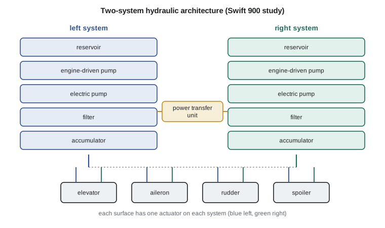
Redundancy follows the safety targets of Lesson 1. Loss of pitch control is catastrophic, so no single hydraulic failure, whether a pump failure, a burst pipe or a leak that empties a reservoir, may remove it. The Swift 900 study has two independent hydraulic systems, left and right, each with an engine-driven pump and an electric pump. Each elevator has two actuators, one on each system, either of which can hold and move the surface. Large airliners commonly have three systems; some recent designs have two hydraulic systems and an electrical backup, such as electro-hydrostatic actuators powered from the electrical network.
Routing matters as much as the count. Two systems that run side by side through the same bay can be lost together to a rotor burst from an engine, a tire burst in the wheel well or a fire. The particular risks analysis described in Lesson 1 checks the routes against these threats, and pipes are separated, shielded or relocated where needed.
Sizing an actuator
The starting point is the hinge moment, the torque the air exerts about the surface's hinge line. It is written with a hinge moment coefficient, the dynamic pressure, the surface area and its chord. The actuator force is the hinge moment divided by the moment arm of the horn the actuator pushes on, plus margin for friction, gusts and the force needed to break free a jammed opposite actuator if the design requires it. The piston area is the force divided by the pressure available at the actuator, which is lower than the system pressure because of losses in the lines and valves.
The flow follows from the rate. The surface must move at a specified rate, often 40 to 60 degrees per second for primary flight controls on a jet, and the rod speed is that angular rate times the moment arm. Flow is piston area times rod speed. Adding the flows of all actuators that might move at once gives the pump's required delivery.
Tomasz Wierzbicki's aerodynamics group supplies the elevator data and Hélène Lavoie's flight controls group the required rate. Arjun's program sizes the actuator at the highest dynamic pressure the Swift 900 study will see at low altitude, 150 m/s at sea level.
# Sizing a Swift 900 elevator actuator: hinge moment, piston area at system pressure, flow for the
# required surface rate, and the hydraulic power drawn; then an electro-hydrostatic actuator option.
import math
rho, V = 1.225, 150.0                 # sea level, highest dynamic pressure case for the design check
q = 0.5 * rho * V**2
S_e, c_e, Ch = 2.1, 0.42, 0.12        # elevator area m2, elevator chord m, hinge moment coefficient (illustrative)
H = Ch * q * S_e * c_e                # hinge moment N m (one side)
arm = 0.080                           # actuator moment arm (horn) m
F = H / arm * 1.5                     # actuator force with 1.5 margin for jams, friction and gusts
p_sys = 20.7e6                        # 3000 psi system
A = F / (p_sys * 0.85)                # 15 percent pressure loss to the actuator
d = math.sqrt(4 * A / math.pi)
rate = math.radians(40.0)             # surface rate, rad/s
v_rod = rate * arm                    # rod speed m/s
Q = A * v_rod                         # flow m3/s
print(f"dynamic pressure {q/1000:.1f} kPa, hinge moment {H/1000:.2f} kN m, actuator force {F/1000:.1f} kN")
print(f"piston area {A*1e4:.1f} cm2 (bore about {d*1000:.0f} mm), rod speed {v_rod*1000:.0f} mm/s")
print(f"flow {Q*60000:.1f} L/min per actuator, hydraulic power at full rate {p_sys*Q/1000:.1f} kW")
n_act = 2
Q_tot = n_act * Q * 60000 + 25.0      # both elevator actuators plus ailerons, rudder, spoilers (25 L/min)
print(f"peak demand on one system {Q_tot:.0f} L/min; engine-driven pump sized for about {Q_tot*1.2:.0f} L/min")
# Electro-hydrostatic actuator: its own motor and pump, drawing electrical power only when moving
eta_eha = 0.65
P_el = p_sys * 0.85 * Q / eta_eha
print(f"\nan electro-hydrostatic actuator would draw about {P_el/1000:.1f} kW electrical at full rate,"
      f" and near zero holding a steady position")
print(f"at 10 percent average activity: {0.1*P_el/1000:.2f} kW average per actuator")dynamic pressure 13.8 kPa, hinge moment 1.46 kN m, actuator force 27.3 kN piston area 15.5 cm2 (bore about 44 mm), rod speed 56 mm/s flow 5.2 L/min per actuator, hydraulic power at full rate 1.8 kW peak demand on one system 35 L/min; engine-driven pump sized for about 43 L/min an electro-hydrostatic actuator would draw about 2.3 kW electrical at full rate, and near zero holding a steady position at 10 percent average activity: 0.23 kW average per actuator
With a hinge moment coefficient of 0.12 the hinge moment is 1.46 kN m. On an 80 mm arm, with a 1.5 margin, the actuator must push 27.3 kN, which at 85 percent of 3000 psi needs a piston area of 15.5 cm², a bore of about 44 mm. Moving the surface at 40 degrees per second needs 5.2 liters per minute and about 1.8 kW of hydraulic power per actuator. With the other surfaces, one system's peak demand is about 35 L/min, and the engine-driven pump is sized for about 43 L/min with margin. These numbers are small by airliner standards, which is why business jets can use compact systems, but they illustrate the method an engineer would use on any aircraft.
| Actuation type | Power source | Strengths | Concerns |
|---|---|---|---|
| Hydraulic servo actuator | Central hydraulic system | High force, stiff, proven, compact | Pipes, leaks, fluid fires, weight of the central system |
| Electro-hydrostatic actuator | Electrical bus; own motor, pump and fluid | No central pipes; power drawn only when moving | Heat in the actuator, electric motor and electronics weight |
| Electromechanical actuator | Electrical bus; motor and gearbox or ball screw | No fluid at all; simple installation | Jamming of the gear train; harder to make fail-safe for primary controls |
| Mechanical cable and pushrod | Pilot force, sometimes with tabs | Simple, no power needed | Limited to forces a pilot can provide |
More-electric actuation
An electro-hydrostatic actuator, or EHA, contains its own small electric motor, a reversible pump and a sealed volume of fluid. It is connected to the aircraft only by wires and draws power only when it moves the surface. The program shows that an EHA doing the same job as the elevator's hydraulic actuator would draw about 2.3 kW of electricity at full rate, but almost nothing when holding a steady position, so at a typical 10 percent activity it averages about 0.2 kW. Several recent airliners use EHAs as a backup to hydraulic actuators on primary surfaces, removing the need for a third hydraulic system.
An electromechanical actuator, or EMA, removes the fluid altogether: an electric motor drives the surface through a gearbox or a ball screw. EMAs are common for trim, flaps and secondary surfaces. For primary flight controls their difficulty is jamming: a seized ball screw holds the surface fixed, and the design must show that a jam is extremely improbable or that the other actuators can overpower it, which is hard with mechanical drive trains. Research continues into jam-tolerant designs.
The Tern Block 2 shows where small aircraft are heading. Its primary flight controls are mechanical, cables and pushrods with aerodynamic balance and tabs, as on most aircraft of its size. Its flaps, trim, landing gear retraction and nose wheel steering are electromechanical, powered from the 28 V bus. There is no hydraulic system except the self-contained brake units, which removes a whole class of maintenance tasks and the fire risk of hydraulic fluid near the hot turboshaft. The trade is the electrical load: the landing gear motor alone draws about 1.5 kW for the 10 seconds it takes to retract, and it appears in the ELA of Lesson 2 under the flight control actuators line.
Hydraulic servo valves and control
A hydraulic actuator is controlled by a servo valve, which meters flow to one side of the piston or the other in proportion to an electrical command, or by a mechanical valve linked to the pilot's controls on older designs. A position sensor on the actuator rod closes the loop, so that the actuator follows the command. In a fly-by-wire aircraft like the Swift 900 study, the flight control computers send commands to the actuators' electronics, often called remote electronic units or actuator control electronics, which run the servo loop locally. The actuators must also behave safely when commands are lost: most primary-surface actuators have a damping mode, in which the piston's two sides are connected through a restrictor so that the surface is free to move but cannot flutter.
Worked problem
Piston area
An aileron actuator must push 18 kN with 18 MPa available at the actuator. What piston area and bore are needed?
Show solution
- \(A = 18\,000/18\times10^6 = 1.0\times10^{-3}\) m² \(= 10\) cm².
- Bore \(= \sqrt{4A/\pi} = \sqrt{4 \times 10^{-3}/3.1416} = 0.0357\) m.
Answer: About 10 cm², a 36 mm bore.
Worked problem
Pump flow
Four actuators each have a piston area of 12 cm² and a maximum rod speed of 80 mm/s. What flow must a pump supply if all four move at once?
Show solution
- Each: \(Q = 12\times10^{-4} \times 0.080 = 9.6\times10^{-5}\) m³/s \(= 5.8\) L/min.
- Four: \(23\) L/min.
Answer: About 23 L/min, before margin.
Worked problem
Hydraulic power
What hydraulic power does a 40 L/min pump deliver at 20.7 MPa?
Show solution
- \(Q = 40/60\,000 = 6.67\times10^{-4}\) m³/s; \(P = pQ = 20.7\times10^6 \times 6.67\times10^{-4} = 13.8\) kW.
Answer: About 13.8 kW of hydraulic power, so the engine must supply about 16 kW of shaft power at a pump efficiency of 0.85.
Common mistakes
MistakeSizing the piston with the full system pressure.
InsteadLine and valve losses reduce the pressure available at the actuator.
MistakeCounting two hydraulic systems as independent when their pipes share a bay.
InsteadA rotor burst, tire burst or fire can take both; routes must be separated.
MistakeAssuming an electromechanical actuator is a drop-in replacement for a hydraulic one on a primary surface.
InsteadJamming must be shown to be extremely improbable or overpowered by the other actuators.
MistakeTreating phosphate ester fluid like ordinary oil.
InsteadIt attacks skin, eyes, paints and some seals; it needs protective equipment and dedicated materials.
Summary and key terms
- Hydraulic systems give large, stiff forces from compact actuators and remain the main actuation power on most jets, usually at 3000 psi, with two or three independent systems for primary controls.
- Actuators are sized from the hinge moment, moment arm and available pressure, and pumps from the sum of actuator flows at the required rates.
- Electro-hydrostatic and electromechanical actuators replace central hydraulics on more-electric aircraft, trading pipes for electrical power and new failure modes.
- The Tern uses mechanical primary controls and electric secondary actuation; the Swift 900 study uses two hydraulic systems.
- Hinge moment
- The aerodynamic torque on a control surface about its hinge line.
- Servo valve
- A valve that meters hydraulic flow in proportion to an electrical command.
- Accumulator
- A pressure vessel that stores hydraulic energy and smooths pressure.
- Power transfer unit
- A device that lets one hydraulic system drive another's pressure without mixing fluids.
- Electro-hydrostatic actuator
- An actuator with its own motor, pump and fluid, powered electrically.
- Ram air turbine
- A small wind-driven turbine deployed to provide emergency hydraulic or electrical power.
Practice problems
Work each problem on paper first, then reveal the answer to check.
In the program, raise the surface rate to 60 degrees per second. What flow does one actuator need?
Show answer
About 7.8 L/min.
Why do many transport aircraft use phosphate ester fluid?
Show answer
For its fire resistance.
What does a damping mode protect against when an actuator loses its command?
Show answer
Surface flutter.
Name one reason electromechanical actuators are less common on primary flight controls.
Show answer
Gear train or ball screw jamming is hard to make extremely improbable.
Why does the Tern avoid a central hydraulic system?
Show answer
To save maintenance and remove hydraulic fluid fire risk near the turboshaft.
At 5000 psi instead of 3000 psi, how does the piston area for the same force change?
Show answer
It falls to about 60 percent.
Lesson quiz · 5 questions
Score 60% or more to complete this lesson.
Create a free account to save your progress, take quizzes and earn a certificate.