
AERO-350 · Lesson 11 of 12 · 25 min
Cockpit displays and flight management
Every system in this course eventually reports to the crew. The flight deck is where the information from air data, inertial and navigation sensors, engines, fuel, electrical and hydraulic systems is turned into displays a person can read at a glance, and where the crew's intentions are turned into commands. It is also where most of the flight management happens: a computer that plans the route, predicts fuel and time, and steers the aircraft along a path in four dimensions. This lesson covers glass cockpit displays, crew alerting, the flight management system and the human factors that tie them together, with the Swift 900 study's flight deck and the Tern Block 2's simpler panel as examples.
From round dials to glass
Older aircraft had a separate mechanical instrument for each quantity: airspeed, attitude, altitude, heading, vertical speed, engine parameters, fuel quantity and many more, arranged in a standard layout called the basic T. Modern flight decks have large flat-panel displays driven by display computers. The primary flight display, PFD, shows attitude in the center with airspeed on a tape to the left, altitude on a tape to the right, vertical speed and heading below, and the autopilot's modes and targets along the top. The navigation display shows the route, other traffic, weather and terrain on a map. Engine indication and crew alerting is shown on a separate display, and systems synoptic pages show schematics of the fuel, electrical, hydraulic and other systems that the crew can call up.
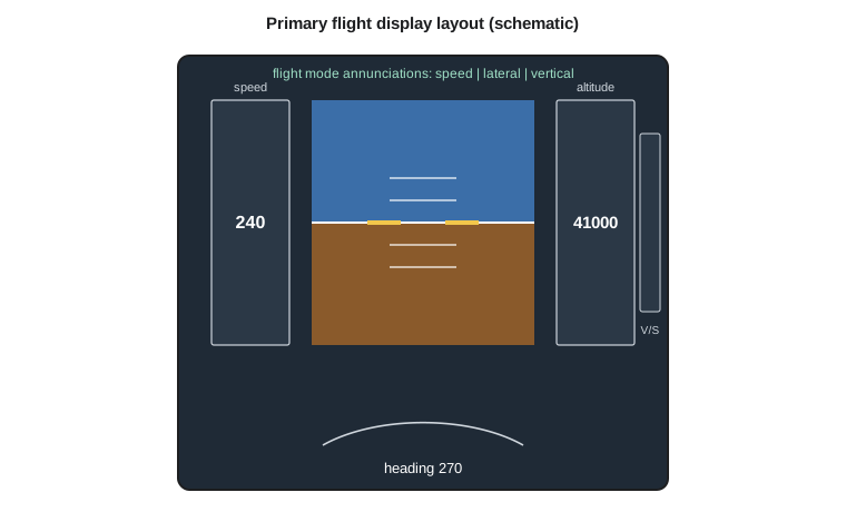
Glass cockpits have advantages beyond saving weight and wiring. Information can be combined: a speed tape shows not only the current speed but its trend, the stall warning speed, the maximum speed and the selected target, in one place. Displays can be reconfigured if one fails, moving the primary flight display to another screen. And software can be updated to add functions without new hardware. The Swift 900 study's flight deck has four large displays and a standby instrument with its own sensors and battery, as Lesson 8 noted. The Tern's has two displays, one for each pilot, and a standby.
Displays bring their own hazards. A display that shows the wrong attitude confidently is worse than a blank one, so display systems compare data from independent sources, flag disagreements and remove information that cannot be trusted rather than show it. Loss of all attitude display is usually classified as catastrophic and misleading attitude as catastrophic too, which is why the display chain needs level A development assurance and independent channels, as Lessons 1 and 12 explain.
Crew alerting
An aircraft can generate hundreds of different alerts, and the crew must notice and respond to the right ones first. Alerting systems follow a consistent hierarchy. The highest level, called a warning, requires immediate crew action; it is shown in red with an aural tone or voice and a master warning light. The next level, a caution, requires immediate awareness and later action; it is shown in amber with a master caution light. Advisories, in cyan or white, require awareness only. Status messages tell maintenance about faults that do not affect the flight. The rules require alerts to be prioritized, so that a fire warning is not buried under a list of cautions caused by the same failure.
Good alerting design tells the crew what is wrong and what to do. Electronic checklists linked to the alert display the procedure, and sensing of switch positions can confirm that each step has been done. The lessons of several accidents in which crews were overwhelmed by cascades of alerts after a single failure have shaped current design: alerts that are consequences of a root cause are suppressed or grouped so that the root cause is clear.
| Alert level | Meaning | Color and cue | Example on the Tern |
|---|---|---|---|
| Highest: warning | Immediate action required | Red, master warning light and aural | Battery thermal runaway, engine fire |
| Second: caution | Immediate awareness, action later | Amber, master caution light and tone | One DC-DC converter failed |
| Third: advisory | Awareness only | Cyan or white | Windshield heat shed |
| Lowest: status | Maintenance information | On a maintenance page | Cooling pump running on its standby motor |
Head-up displays and vision systems
A head-up display projects flight information on a transparent combiner in front of the pilot's eyes, focused at infinity, so the pilot can see the guidance and the outside world together. It is especially useful in the last stages of an approach and allows lower landing minima with appropriate approval. Enhanced vision systems use infrared cameras to show the runway and terrain through darkness and some kinds of haze. Synthetic vision draws a three-dimensional picture of terrain and runways from a database on the primary flight display. Combined vision systems overlay the two. Rules in both countries allow operational credit, such as lower minima, for certified enhanced flight vision systems under specific conditions.
The flight management system
The flight management system, FMS, is the aircraft's navigator and planner. The crew enters or loads the flight plan: departure, route, arrival and approach, using the procedures in the navigation database of Lesson 9. The FMS computes the aircraft's position by blending GNSS, inertial and radio data, calculates the lateral path with its turns and transitions, and with performance data for the aircraft and engines predicts the vertical profile, the time at each waypoint and the fuel remaining. It sends steering commands to the autopilot or flight director in lateral navigation, LNAV, and vertical navigation, VNAV, modes.
Vertical navigation is where the FMS saves most fuel. In descent it plans an idle-thrust path from the top of descent to the first constraint, so that the engines do not have to add thrust to level off early. Pilots carry a simple rule of thumb, the 3-to-1 rule, which says to start down three nautical miles for every thousand feet to lose. The FMS does better, using the actual weight, the forecast winds and the descent speed.
# Flight management: top of descent from the 3-to-1 rule and from an idle descent path,
# descent time and fuel, and a fuel prediction at destination against required reserves.
import math
alt_cruise_ft, field_ft = 41000.0, 820.0
gs_desc_kt = 330.0                     # average ground speed in the descent
loss = alt_cruise_ft - field_ft - 1500  # descend to 1500 ft above the field at the approach fix
print(f"altitude to lose: {loss:.0f} ft")
print(f"3-to-1 rule: start down {3*loss/1000:.0f} NM before the fix")
for gamma in (2.5, 3.0):
    d = loss / math.tan(math.radians(gamma)) / 6076
    t = d / gs_desc_kt * 60
    print(f"idle path at {gamma:.1f} deg: {d:5.0f} NM, about {t:4.1f} min, descent rate {gs_desc_kt*6076/60*math.tan(math.radians(gamma)):5.0f} ft/min")
# Tailwind in the descent stretches the distance; the FMS rebuilds the path from the forecast
for wind in (-40, 0, 40):
    gs = gs_desc_kt + wind
    d = loss / math.tan(math.radians(2.5)) / 6076 * gs / gs_desc_kt
    print(f"   {'tail' if wind>0 else 'head' if wind<0 else 'calm'} {abs(wind):2d} kt: top of descent {d:5.0f} NM out")
# Fuel prediction: cruise 1150 NM at 460 kt ground speed burning 640 kg/h in total, descent 120 kg
fob, burn_h, dist, gs = 2500.0, 640.0, 1150.0, 460.0
trip = burn_h * dist / gs + 120.0
alt_fuel, final = 380.0, 0.5 * 560.0    # alternate fuel and 30 minutes of holding at 560 kg/h
land = fob - trip
print(f"\ntrip fuel {trip:.0f} kg, predicted on landing {land:.0f} kg; required alternate + final reserve "
      f"{alt_fuel + final:.0f} kg -> " + ("OK" if land >= alt_fuel + final else "plan a fuel stop"))
gs2 = 420.0
trip2 = burn_h * dist / gs2 + 120.0
print(f"with a 40 kt stronger headwind: trip {trip2:.0f} kg, landing {fob - trip2:.0f} kg -> "
+ ("OK" if fob - trip2 >= alt_fuel + final else "plan a fuel stop"))altitude to lose: 38680 ft 3-to-1 rule: start down 116 NM before the fix idle path at 2.5 deg: 146 NM, about 26.5 min, descent rate 1459 ft/min idle path at 3.0 deg: 121 NM, about 22.1 min, descent rate 1751 ft/min head 40 kt: top of descent 128 NM out calm 0 kt: top of descent 146 NM out tail 40 kt: top of descent 163 NM out trip fuel 1720 kg, predicted on landing 780 kg; required alternate + final reserve 660 kg -> OK with a 40 kt stronger headwind: trip 1872 kg, landing 628 kg -> plan a fuel stop
Descending from 41 000 ft to 1500 ft above a field at 820 ft, the 3-to-1 rule gives a top of descent 116 NM out. An idle path of 2.5 degrees starts 146 NM out and takes about 27 minutes at a descent rate under 1500 ft/min, more comfortable for the passengers' ears, as Lesson 5 explained. A 40 kt tailwind stretches the path to 163 NM. The FMS recomputes the top of descent continuously with the forecast and measured winds.
The second part shows the FMS's fuel prediction doing its most important job. With 2500 kg on board for a 1150 NM leg, the predicted landing fuel of 780 kg covers the 660 kg of alternate and final reserve. If the headwind is 40 kt stronger than planned, the predicted landing fuel falls to 628 kg, below the required reserves, and the FMS alerts the crew early enough to plan a fuel stop or a closer alternate. The fuel reserve rules differ in detail between the two countries and between commercial and private operations, but every set of rules requires a final reserve and the means to monitor fuel en route.
Electronic flight bags and performance
Electronic flight bags, tablets or installed computers, have replaced paper manuals, charts and performance tables on most flight decks. They compute take-off and landing performance from the runway condition reports mentioned in Lesson 7, the weight, temperature and wind, and show moving maps with the aircraft's position on airport charts. Their software and data must be approved for the purposes they are used for, and their mounting and power must not interfere with other systems.
Human factors
The flight deck is designed around people. Controls must be reachable and distinguishable by touch, displays readable in direct sunlight and at night, and procedures workable when the crew is tired or under stress. Automation brings its own human factors: mode confusion, in which the crew believes the autopilot is doing one thing when it is doing another, has contributed to several accidents. Designers reduce it with clear mode annunciations, consistent logic and training. Certification includes human factors evaluations in simulators and flight test, with representative pilots assessing workload and error potential, and the FAA has published guidance for applicants on this subject.
The Tern Block 2 adds a new human factors problem: energy management. A hybrid aircraft's crew must understand how much battery and fuel energy remains, how much each phase of flight will use, and when the turboshaft must run. Hélène Lavoie's team has designed an energy page that shows battery state of charge for each string, the turboshaft's status, the predicted energy at destination and a simple range ring. The special conditions for the Tern require indications of usable energy that cannot mislead the crew, and the display's software is assigned level B because erroneous battery state of charge was classified as hazardous in Lesson 1's functional hazard assessment.
Worked problem
The 3-to-1 rule
An aircraft at 35 000 ft must reach 3000 ft at a fix. Where should it start down by the 3-to-1 rule?
Show solution
- Altitude to lose: 32 000 ft; distance: \(3 \times 32 = 96\) NM.
Answer: About 96 NM before the fix, adjusted for wind.
Worked problem
Descent rate
What descent rate keeps a 3 degree path at 300 kt ground speed?
Show solution
- \(300 \times 6076/60 \times \tan 3^\circ = 30\,380 \times 0.0524 = 1592\) ft/min.
Answer: About 1600 ft/min; a handy check is ground speed times 5.
Worked problem
Fuel at destination
An aircraft has 1800 kg on board, burns 600 kg/h at 400 kt ground speed for 800 NM, and needs 100 kg for descent and approach. What is its predicted landing fuel?
Show solution
- Cruise: \(600 \times 800/400 = 1200\) kg; trip \(= 1300\) kg; landing \(= 500\) kg.
Answer: 500 kg, to be compared with the required alternate and final reserves.
Common mistakes
MistakeShowing information whose source cannot be trusted.
InsteadDisplay systems compare sources and remove untrustworthy data rather than show it.
MistakeGiving every alert the same priority.
InsteadAlerts are ranked from warnings down to advisories, and grouped so the root cause is clear.
MistakeUsing the 3-to-1 rule without allowing for wind.
InsteadTailwinds stretch and headwinds shorten the descent distance.
MistakeAssuming the crew always knows the autopilot mode.
InsteadMode confusion is a known hazard; clear annunciations and training are needed.
Summary and key terms
- Glass cockpits combine air data, attitude, navigation and systems information on primary flight, navigation and alerting displays, with independent sources compared so that untrustworthy data is removed.
- Crew alerting follows a hierarchy of warnings, cautions, advisories and status messages, prioritized so the root cause is clear.
- Head-up displays and vision systems help in low visibility.
- The flight management system plans the route, predicts time and fuel, and flies lateral and vertical paths, including idle descents that save fuel, and alerts the crew when reserves are at risk.
- Human factors design and the Tern's energy display complete the picture.
- Primary flight display
- The display showing attitude, airspeed, altitude, vertical speed, heading and autopilot modes.
- Crew alerting system
- The system that presents warnings, cautions and advisories to the crew in priority order.
- Head-up display
- A transparent display that shows flight information in the pilot's forward view.
- Flight management system
- The computer that plans and flies the route and predicts time and fuel.
- Top of descent
- The point at which the descent from cruise begins.
- Mode confusion
- A mismatch between what the crew thinks the automation is doing and what it is doing.
Practice problems
Work each problem on paper first, then reveal the answer to check.
In the program, what top of descent does a 3.0 degree path give with a 40 kt tailwind?
Show answer
About 135 NM.
What color and cue is used for a warning?
Show answer
Red, with a master warning light and aural alert.
In the program, with the stronger headwind, how much more fuel is needed to meet the reserves?
Show answer
About 32 kg.
What is synthetic vision?
Show answer
A three-dimensional picture of terrain and runways drawn from a database.
Why is the Tern's energy display software assigned level B?
Show answer
Erroneous battery state of charge was classified as hazardous.
What does VNAV do in descent?
Show answer
It flies an idle-thrust path planned by the FMS to meet constraints.
Lesson quiz · 5 questions
Score 60% or more to complete this lesson.
Create a free account to save your progress, take quizzes and earn a certificate.