
AERO-330 · Lesson 2 of 12 · 24 min
Longitudinal static stability
Sam Littlechild describes good longitudinal stability in pilot's language: 'If a gust pitches the nose up, I want the airplane to push it back down by itself, and I want to feel that it is doing it.' Engineers turn that into a statement about the pitching moment. Arjun's first task in the stability and control study is to show that the Tern Block 2, with its new wing and slightly longer fuselage, still has that tendency at every center of gravity position in the loading envelope, and to find how much of it the horizontal tail must supply.
Static stability is about the initial tendency after a disturbance, not about what happens over time. An aircraft is statically stable in pitch if an increase in angle of attack produces a nose-down pitching moment that tends to reduce it again. Whether the motion that follows dies away smoothly, oscillates or diverges is a question of dynamic stability, the subject of Lessons 6 and 7. Static stability is necessary for dynamic stability in a conventional aircraft but does not guarantee it.
The pitching moment curve
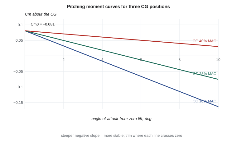
Measure the pitching moment coefficient about the center of gravity, \(C_m\), at several angles of attack with the elevator fixed, and plot it. Two features of that curve decide everything. To fly steadily the aircraft must be trimmed: \(C_m = 0\) at a positive lift coefficient. To be stable the curve must slope downward: \(C_{m_\alpha} = dC_m/d\alpha < 0\). Put together, the curve must start positive at zero lift and cross zero at the flight lift coefficient.
Here \(\alpha\) is measured from the zero-lift attitude of the whole aircraft. A wing alone, with positive camber, has a negative \(C_{m_0}\) about its aerodynamic center, so a conventional aircraft relies on the tail, set at a negative incidence relative to the wing, to provide the positive \(C_{m_0}\). A flying wing must instead use reflexed aerofoils or sweep and twist, which is one reason why tailless designs are harder to balance.
Contribution of the wing and body
Take moments about the CG, which lies a distance \(h\bar c\) behind the wing's leading edge on the mean aerodynamic chord, while the wing-body aerodynamic center lies at \(h_{ac}\bar c\). The wing-body lift acts at its aerodynamic center, where the pitching moment does not change with angle of attack. If the CG is aft of the aerodynamic center, lift acting ahead of the CG produces a nose-up moment that grows as lift grows: the wing on its own is destabilizing. If the CG is forward of the aerodynamic center, the wing is stabilizing.
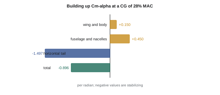
The fuselage and engine nacelles add a further destabilizing term. A body in a flow produces a pitching moment that increases with angle of attack, roughly in proportion to its volume ahead of the wing, a result due to Munk's slender-body theory and corrected with empirical factors in handbook methods. For the Tern, with two nacelles projecting well ahead of the wing, the fuselage and nacelles together contribute about +0.45 per radian, three times the wing's own contribution at mid CG.
The horizontal tail
The tail is the main stabilizing surface. A small increase in aircraft angle of attack raises the tail's angle of attack too, but by less, because the wing's downwash also increases. The tail's lift increases and, acting at a long arm behind the CG, produces a nose-down moment. Its contribution is
where \(\eta\) is the ratio of dynamic pressure at the tail to free-stream dynamic pressure, \(a_t\) is the tail lift slope, \(d\varepsilon/d\alpha\) is the rate at which downwash grows with angle of attack, and \(V_H\) is the tail volume coefficient. The tail volume coefficient captures the design trade: a large tail on a short arm or a small tail on a long arm give similar stability. Typical values are about 0.5 for light aircraft and 0.7 to 1.0 for transports. The Tern's horizontal tail, 4.6 m² (49.5 ft²) on a 7.6 m arm, gives 0.72.
The downwash factor is easy to underestimate. Behind a lifting wing the flow is turned downward by an angle that, for an elliptic loading, is roughly \(2C_L/(\pi A)\) at the wing and somewhat more far behind it. Its derivative \(d\varepsilon/d\alpha\) is typically 0.3 to 0.5. For the Tern's high-aspect-ratio wing and low-set tail, the tunnel model gave 0.45, which removes nearly half of the tail's potential effectiveness. Slipstream from the propellers also changes both \(\eta\) and the downwash, which is why power-on and power-off tunnel runs give different answers and why the Tern's stability is checked at idle and at maximum continuous power.
# Longitudinal static stability of the Tern Block 2: build Cm-alpha from the wing, the
# fuselage and the tail, then see how it changes as the center of gravity moves aft.
S, c = 28.0, 1.73                # wing area m2, mean aerodynamic chord m
a_w = 5.04                       # wing-body lift slope per radian (from AERO-300)
St, lt = 4.6, 7.6                # horizontal tail area m2, tail arm (wing ac to tail ac) m
a_t = 4.10                       # tail lift slope per radian
eta = 0.92                       # tail dynamic pressure ratio
de_da = 0.45                     # downwash gradient d(epsilon)/d(alpha)
h_ac = 0.25                      # wing-body aerodynamic center, fraction of MAC
dCm_fus = 0.45                   # destabilizing fuselage and nacelle contribution per radian
VH = St * lt / (S * c)           # tail volume coefficient
a = a_w + a_t * eta * (St / S) * (1 - de_da)   # whole-aircraft lift slope
print(f"tail volume coefficient VH = {VH:.3f}, aircraft lift slope a = {a:.2f} per rad")
print(" CG (%MAC)   wing+body   tail      total Cm_alpha   Cm_alpha/a")
for h in (0.15, 0.20, 0.25, 0.30, 0.35, 0.40, 0.45):
    wing = a_w * (h - h_ac) + dCm_fus
    tail = -eta * VH * a_t * (1 - de_da)
    tot = wing + tail
    print(f"  {100*h:5.0f}      {wing:+.3f}     {tail:+.3f}       {tot:+.3f}         {tot/a:+.3f}")
# Cm at zero lift from wing camber and tail incidence, so the aircraft can trim at positive lift
Cm_ac = -0.085                   # wing-body pitching moment about its ac (cambered NACA 44xx)
it, eps0 = -2.0 / 57.3, 1.5 / 57.3   # tail incidence and downwash at zero lift, radians
Cm0 = Cm_ac + eta * VH * a_t * (eps0 - it)
h = 0.28
Cma = a_w * (h - h_ac) + dCm_fus - eta * VH * a_t * (1 - de_da)
alpha_trim = -Cm0 / Cma
print(f"\nCm0 = {Cm0:+.3f}; at CG {100*h:.0f}% MAC Cm_alpha = {Cma:+.3f} per rad")
print(f"trim angle of attack (elevator neutral) {alpha_trim*57.3:.1f} deg from zero lift, CL = {a*alpha_trim:.2f}")tail volume coefficient VH = 0.722, aircraft lift slope a = 5.38 per rad
CG (%MAC) wing+body tail total Cm_alpha Cm_alpha/a
15 -0.054 -1.497 -1.551 -0.288
20 +0.198 -1.497 -1.299 -0.241
25 +0.450 -1.497 -1.047 -0.195
30 +0.702 -1.497 -0.795 -0.148
35 +0.954 -1.497 -0.543 -0.101
40 +1.206 -1.497 -0.291 -0.054
45 +1.458 -1.497 -0.039 -0.007
Cm0 = +0.081; at CG 28% MAC Cm_alpha = -0.896 per rad
trim angle of attack (elevator neutral) 5.2 deg from zero lift, CL = 0.49The table shows the main lesson in numbers. The tail's contribution, about −1.50 per radian, does not change with CG position, but the wing and body contribution grows by about 0.25 per radian for every 5 percent of chord the CG moves aft. At 15 percent the total is −1.55; at 45 percent it has fallen to −0.04, essentially neutral. The ratio \(C_{m_\alpha}/a\) in the last column is minus the static margin, which Lesson 3 develops. The second part shows how the tail's negative incidence produces \(C_{m_0} = +0.081\), enough to trim at a lift coefficient of 0.49 with the elevator neutral and the CG at 28 percent: close to the Tern's cruise lift coefficient, which is what designers aim for so that the elevator and trim tab spend most of the flight near neutral and add little drag.
Power effects and other contributions
The propellers of a turboprop add their own pitching moments. A propeller at an angle of attack produces a normal force in its own plane, and for a tractor propeller ahead of the CG this is destabilizing. The thrust line, if it lies below the CG, gives a nose-up moment that grows with power. The slipstream washes over the inner wing and the tail, raising the tail's dynamic pressure but also changing its downwash. On the Tern these effects together reduce \(|C_{m_\alpha}|\) by roughly 10 percent at full power, and the aft CG limit is set with that in mind. Flaps add a nose-down \(C_{m_0}\) increment and change the downwash at the tail, so trim and stability are checked in each flap setting. the FAA flight requirements of 14 CFR Part 23, including 23.2135 on controllability and 23.2145 on stability require static longitudinal stability throughout normal operations, so the analysis must cover every configuration the aircraft will fly in, not just clean cruise.
Measuring static stability in flight
A wind tunnel model gives the pitching moment curve directly, but in flight nobody can read \(C_m\) off an instrument. Flight test engineers infer stability from the elevator. In steady flight the aircraft is always trimmed, so the elevator angle needed to trim at each speed tells what moment the tail must supply. The more stable the aircraft, the more the elevator must move as speed changes, so the slope of trim elevator angle against lift coefficient is a direct measure of static stability. Lesson 4 derives the relation; Lesson 3 uses it to locate the neutral point by flying at two or three CG positions and extrapolating the slope to zero.
For the Block 2 program, Prairiewind Aerospace will fly the aircraft with ballast placed to move the CG to the forward limit, mid-range and the aft limit, and at each CG Sam will trim at five or six speeds from near the stall to the maximum operating speed. The flight test engineer plots elevator angle against lift coefficient for each CG, measures the slopes and plots the slopes against CG position. Where the line crosses zero slope is the stick-fixed neutral point, measured rather than predicted. Arjun's prediction will be judged against that measurement, and the tunnel-based downwash and fuselage estimates will be corrected if they disagree. That loop, prediction followed by flight test and correction, is the normal pattern of stability and control work, and it is why every prediction in this course is written so it can be checked against a measurement.
Worked problem
Is the wing alone stable?
A wing has lift slope 5.0 per radian and its aerodynamic center at 25 percent of the mean chord. Find its \(C_{m_\alpha}\) about a CG at 20 percent and at 32 percent.
Show solution
- At 20 percent: \(5.0 \times (0.20 - 0.25) = -0.25\) per radian: stable.
- At 32 percent: \(5.0 \times (0.32 - 0.25) = +0.35\) per radian: unstable.
Answer: A wing alone is stable only if the CG is ahead of its aerodynamic center. That is too restrictive for a practical loading range, which is why conventional aircraft carry a tail.
Worked problem
Tail contribution
A tail of 5.0 m² sits 8.0 m behind the CG of an aircraft with a 30 m² wing and 1.8 m mean chord. With \(a_t = 4.0\) per radian, \(\eta = 0.9\) and \(d\varepsilon/d\alpha = 0.40\), find the tail volume coefficient and the tail contribution to \(C_{m_\alpha}\).
Show solution
- \(V_H = 5.0 \times 8.0/(30 \times 1.8) = 0.741\).
- \(C_{m_\alpha,t} = -0.9 \times 0.741 \times 4.0 \times (1 - 0.40) = -1.60\) per radian.
Answer: If the downwash gradient rose to 0.50, for example because of a different tail height, the contribution would fall to −1.33, a loss of one sixth.
Common mistakes
MistakeCalling an aircraft stable because the motion after a gust dies out.
InsteadThat is dynamic stability; static stability is only the sign of the initial restoring moment.
MistakeIgnoring downwash at the tail.
InsteadThe factor 1 − dε/dα typically removes 30 to 50 percent of the tail's effectiveness.
MistakeThinking a cambered wing alone can trim and be stable.
InsteadPositive camber gives a negative Cm0, so a tail or reflex is needed.
MistakeChecking stability only in clean cruise.
InsteadPower, flaps and gear change Cm0 and Cm-alpha and must be checked too.
Summary and key terms
- An aircraft is statically stable in pitch when Cm-alpha about the CG is negative, and it can trim at positive lift only if Cm0 is then positive.
- The wing-body contribution depends on the distance between the CG and the aerodynamic center and becomes destabilizing as the CG moves aft.
- Fuselage and nacelles are destabilizing.
- The horizontal tail stabilizes in proportion to its volume coefficient, lift slope and dynamic pressure ratio, reduced by downwash.
- Power and flaps change both terms and must be included.
- Static stability
- The tendency of the initial moment after a disturbance to restore the trimmed state.
- Cm-alpha
- The slope of the pitching moment coefficient with angle of attack; negative for stability.
- Cm0
- The pitching moment coefficient at zero lift; positive for a stable aircraft to trim.
- Tail volume coefficient
- S_t l_t/(S c), the size of the tail relative to the wing.
- Downwash gradient
- The rate of change of downwash angle at the tail with angle of attack.
- Dynamic pressure ratio
- Tail dynamic pressure divided by free-stream dynamic pressure.
Practice problems
Work each problem on paper first, then reveal the answer to check.
What two conditions must the Cm-alpha curve satisfy for stable trimmed flight?
Show answer
Cm = 0 at a positive lift coefficient, with a negative slope.
Why is the fuselage destabilizing?
Show answer
A body's pitching moment grows with angle of attack, mostly from its volume ahead of the wing.
Double the tail arm with the same tail area. What happens to VH?
Show answer
It doubles.
In the program, raise de_da to 0.55. What is Cm-alpha at 28 percent?
Show answer
Less negative, about −0.62 per radian.
Why aim to trim near the cruise lift coefficient with the elevator neutral?
Show answer
To minimize trim drag and elevator use for most of the flight.
How does a tractor propeller ahead of the CG affect pitch stability?
Show answer
Its normal force at angle of attack is destabilizing.
Lesson quiz · 5 questions
Score 60% or more to complete this lesson.
Create a free account to save your progress, take quizzes and earn a certificate.