
AERO-310 · Lesson 6 of 12 · 24 min
Idealized wing boxes
The smeared-cover model of Lesson 3 treated the stringers as if they were spread evenly through the skin. That gives the right bending stiffness, but it hides the most important feature of a real wing cover: the load is concentrated in the stringers and spar caps, while the thin skin between them, once it has buckled, carries little direct stress and works mainly in shear. The classic way to capture that behavior by hand, before computers made finite element models routine, is structural idealization. It remains the language of stress engineering today, because it shows clearly where the loads go. Arjun's task this week is to build the idealized model of the Tern root section and to use it for both bending stresses and shear flows.
The idea of booms
In an idealized section, all the material that carries direct stress is lumped into concentrated areas called booms, located at the stringers and spar caps. The walls between booms are assumed to carry only shear flow, with no direct stress. For bending, each boom has an area \(B\); for shear, each wall has a thickness \(t\) and carries a constant shear flow between booms. The approximation is good when the stringers and caps carry most of the direct load, which is true for a stiffened wing cover and even more true once the skin has buckled.
The skin still contributes some direct stress capability, and that contribution is added to the adjacent booms. For a panel of thickness \(t_D\) and width \(b\) between booms 1 and 2, with direct stresses \(\sigma_1\) and \(\sigma_2\), matching the moment of the stress distribution gives an addition to boom 1 of
where \(A_1\) is the area of the stringer or cap itself. For a cover panel in pure bending, both booms are at nearly the same height, the stress ratio is close to one, and each boom receives about half the panel. For a spar web, the booms at the top and bottom have stresses of opposite sign, the ratio is −1, and each receives \(t_D b/6\), the familiar result for a web in bending. Because the ratio depends on the type of loading, an idealization made for bending about one axis is not strictly right for bending about another, though the difference is usually small.
Bending stresses in an idealized section
With booms in place, section properties become sums. For a section symmetric about its horizontal axis, \(I_{xx} = \sum B_r y_r^2\), and the direct stress in boom \(r\) is \(\sigma_r = M_x y_r/I_{xx}\). For unsymmetric sections the general formula of Lesson 3 applies, with the integrals replaced by sums.
Shear flows in an idealized section
Between booms, the shear flow is constant, because the walls carry no direct stress. At each boom it changes by an amount equal to the rate at which the boom's direct load changes along the span. For a section symmetric about the x axis under vertical shear,
For an open idealized section, start at a free edge with zero flow and step from boom to boom. For a closed section, cut one wall, step around the cell to get the open-section flows \(q_b\), then add a constant \(q_{s,0}\) found from a moment condition or, if the load passes through the shear center, from zero twist. This is exactly the method of Lesson 5, now made simple by the step-wise changes at the booms.
The Tern root section
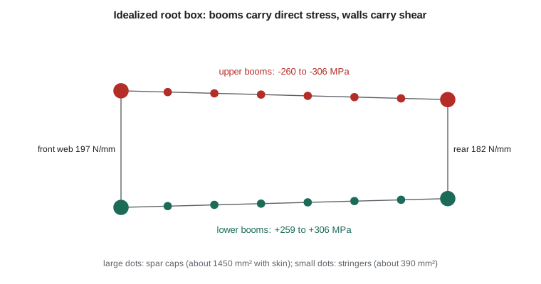
Arjun's first-pass model follows the layout the structures team started from: front and rear spar caps of 1200 mm² each, six Z stringers of 160 mm² in each cover between the spars, 1.6 mm skins and 3 mm spar webs. The box is 1020 mm wide and tapers in depth from 304 mm at the front spar to 258 mm at the rear. Each boom collects its own stringer or cap area plus its share of the adjacent skin and web.
# Idealized root wing box: booms from spar caps, stringers and skin; bending stresses and shear flows
w, fs, rs = 1020.0, 304.0, 258.0           # mm
tskin, tweb = 1.6, 3.0
cap, stringer = 1200.0, 160.0               # mm2: each spar cap, each Z stringer
nstr = 6                                    # stringers per cover between the spars
def ytop(x): return fs / 2 + (rs - fs) / 2 * x / w
xs = [w * i / (nstr + 1) for i in range(nstr + 2)]
# booms listed clockwise from the front spar top: top cover left to right, then bottom cover right to left
booms = [(x, ytop(x)) for x in xs] + [(x, -ytop(x)) for x in reversed(xs)]
n = len(booms)
def seg_t(i):  # wall from boom i to boom i+1
    j = (i + 1) % n
    return tweb if booms[i][0] == booms[j][0] else tskin
area = []
for i, (x, y) in enumerate(booms):
    B = cap if x in (0.0, w) else stringer
    for j in ((i - 1) % n, (i + 1) % n):
        xj, yj = booms[j]
        b = ((x - xj) ** 2 + (y - yj) ** 2) ** 0.5
        t = seg_t(min(i, j) if abs(i - j) == 1 else max(i, j))
        B += t * b / 6 * (2 + yj / y)        # skin idealization with the stress ratio sigma_j / sigma_i = y_j / y_i
    area.append(B)
Ixx = sum(B * y * y for B, (x, y) in zip(area, booms))
print(f"{n} booms; total boom area {sum(area):.0f} mm2; Ixx = {Ixx/1e6:.1f}e6 mm4")
Mx = -420.7e6
for i in (0, 4, nstr + 1, nstr + 2):
    x, y = booms[i]
    print(f"   boom at x = {x:6.1f} mm, y = {y:6.1f} mm, area {area[i]:6.0f} mm2, stress {Mx * y / Ixx:7.1f} MPa")
# shear flows for Sy = 106.9 kN (upward on the wing, ultimate): open-section flows from a cut in the top skin
Sy = 106.9e3
qb = [0.0] * n                               # qb[i] = flow in wall from boom i to boom i+1 (clockwise)
for k in range(1, n):
    x, y = booms[k]
    qb[k] = qb[k - 1] - Sy / Ixx * area[k] * y
qb[0] = qb[n - 1] - Sy / Ixx * area[0] * booms[0][1]      # closes back to the cut (should return to 0)
L = []; A2 = 0.0
for i in range(n):
    (x1, y1), (x2, y2) = booms[i], booms[(i + 1) % n]
    L.append(((x2 - x1) ** 2 + (y2 - y1) ** 2) ** 0.5)
    A2 += 0.5 * (x1 * y2 - x2 * y1)
A2 = abs(A2)
# Sy through the shear center: no twist, so the integral of q ds / t around the cell is zero
q0 = -sum(qb[i] * L[i] / seg_t(i) for i in range(n)) / sum(L[i] / seg_t(i) for i in range(n))
q = [v + q0 for v in qb]
# moment of the shear flows about the front spar top boom fixes the shear center position
Mq = 0.0
for i in range(n):
    (x1, y1), (x2, y2) = booms[i], booms[(i + 1) % n]
    Mq += q[i] * (x1 * y2 - x2 * y1)
xsc = abs(Mq) / Sy
iw_rear = nstr + 1; iw_front = n - 1
print(f"Rear spar web {abs(q[iw_rear]):.1f} N/mm, front spar web {abs(q[iw_front]):.1f} N/mm")
print(f"Shear center about {xsc:.0f} mm aft of the front spar ({100*(0.15*2270 + xsc)/2270:.0f} % chord)")
print(f"Web shear stresses: front {abs(q[iw_front])/tweb:.0f} MPa, rear {abs(q[iw_rear])/tweb:.0f} MPa")16 booms; total boom area 10547 mm2; Ixx = 209.3e6 mm4 boom at x = 0.0 mm, y = 152.0 mm, area 1468 mm2, stress -305.6 MPa boom at x = 582.9 mm, y = 138.9 mm, area 393 mm2, stress -279.2 MPa boom at x = 1020.0 mm, y = 129.0 mm, area 1447 mm2, stress -259.3 MPa boom at x = 1020.0 mm, y = -129.0 mm, area 1447 mm2, stress 259.3 MPa Rear spar web 181.7 N/mm, front spar web 196.9 N/mm Shear center about 457 mm aft of the front spar (35 % chord) Web shear stresses: front 66 MPa, rear 61 MPa
The sixteen booms total about 10 500 mm². The corner booms, each a 1200 mm² cap plus its share of skin and web, come to about 1450 mm². The stringer booms come to about 390 mm², of which only 160 mm² is the stringer itself: the rest is skin. The second moment of area, 209 × 10⁶ mm⁴, is less than the smeared model's 254 × 10⁶, because the idealization gives the webs only their bending share and treats the skin a little more conservatively. As a result, the bending stresses are higher: 306 MPa in compression at the front spar top boom and 259 MPa at the rear. These are the stresses the upper cover must carry without buckling, the problem of Lessons 8 and 9.
For shear, the program applies the ultimate root shear of 107 kN through the shear center. The open-section flows from the cut are corrected by a constant flow chosen so that the box does not twist. The front spar web then carries 197 N/mm and the rear spar web 182 N/mm. In 3 mm webs, that is 66 and 61 MPa of shear stress, comfortably below the shear strength of aluminum alloy but high enough that web buckling must be checked. Taking moments of all the wall flows about the front spar top shows that their resultant acts about 457 mm aft of the front spar, at roughly 35 percent of the local chord. That is the shear center, and every load offset from it adds torque to the box.
What idealization tells a designer
The idealized model makes the load paths visible. Most of the bending is carried by the four corner booms, which is why spar caps are heavy, carefully designed members. The stringers carry the rest, sharing it with the skin they stiffen. The shear force goes mainly down the spar webs, with the covers carrying modest flows that change at every stringer. Any torque adds a constant flow around the whole box, loading covers and webs alike. A designer who sees these paths can make sensible choices: thicken the webs where shear is high, grow the caps where bending is high, add stringers where the skin buckles too early.
Idealization also explains the behavior of structure after the skin buckles. A buckled skin panel sheds direct load to the stringers next to it, so its effective contribution to the booms shrinks, exactly as the effective-width method of Lesson 9 quantifies. Many aircraft are designed to let the skin buckle at loads below limit load, as long as the stringers carry on; idealization with reduced skin contributions models that state well.
Finally, the method is the basis for checking computer models. A finite element model of the Tern wing will have thousands of elements, but at any section the sum of boom loads times their heights must still equal the bending moment, and the sum of web shear flows times their heights must still equal the shear force. A stress engineer who can do the idealized calculation by hand will notice at once if a model is wrong, which Lesson 12 returns to.
Worked problem
Boom area from a skin panel
A cover panel 150 mm wide and 1.6 mm thick lies between two stringers of 160 mm², both at the same height. Find the area of each boom.
Show solution
- Stress ratio \(\sigma_2/\sigma_1 = 1\), so the skin adds \(t_D b/6 \times 3 = t_D b/2 = 1.6 \times 150/2 = 120\) mm² to each boom from this panel.
- With panels on both sides of an interior stringer, the stringer boom receives 120 mm² from each: \(B = 160 + 240 = 400\) mm².
Answer: The skin more than doubles the effective area of each stringer in bending, as long as it has not buckled.
Worked problem
Shear flow in a two-boom web
A spar is idealized as two booms of 1500 mm² at \(y = \pm 140\) mm joined by a web. It carries a vertical shear of 50 kN. Find the web shear flow.
Show solution
- \(I_{xx} = 2 \times 1500 \times 140^2 = 58.8 \times 10^6\) mm⁴.
- Starting from zero above the top boom: \(q = -S_y B y/I = -50\,000 \times 1500 \times 140/58.8 \times 10^6 = -179\) N/mm.
- Check: \(q \times h = 179 \times 280 = 50\,000\) N.
Answer: With all the direct-stress area in the booms, the web carries a uniform shear flow equal to the shear force divided by the distance between the booms.
Common mistakes
MistakeGiving each boom half of the web area for bending.
InsteadFor a web in bending the stress ratio is −1, so each boom receives tb/6, not tb/2.
MistakeForgetting to close the shear flow in a closed section.
InsteadAfter the open-section flows, add the constant flow from a moment or zero-twist condition.
MistakeAssuming the shear flow varies within a wall between booms.
InsteadIn the idealized model, walls carry constant shear flow; it changes only at booms.
MistakeUsing an idealization made for unbuckled skin after the skin has buckled.
InsteadReduce the skin contribution using effective width.
Summary and key terms
- Idealization lumps direct-stress material into booms and treats walls as carrying only shear flow.
- Skin adds area to adjacent booms by t_D b/6 × (2 + σ2/σ1).
- Bending stress follows from sums over booms; shear flow is constant between booms and steps at each boom by S_y B y/I.
- Closed idealized sections are closed with a constant flow from moments or zero twist.
- For the Tern root first-pass model, upper boom stresses reach 306 MPa at ultimate load, the spar webs carry about 190 N/mm, and the shear center sits near 35 percent chord.
- Boom
- A concentrated area that carries the direct stress in an idealized section.
- Structural idealization
- Replacing a stiffened section by booms carrying direct stress and walls carrying shear.
- Closing shear flow
- The constant flow added to an open-section solution to satisfy a closed cell.
- Spar cap
- The heavy flange of a spar that carries most of the bending at the corners of the box.
- Load path
- The route by which load travels through the structure to the supports.
Practice problems
Work each problem on paper first, then reveal the answer to check.
A web 300 mm deep and 3 mm thick sits between booms with stresses of +200 and −200 MPa. What does it add to each boom?
Show answer
tb/6 × (2 − 1) = 3 × 300/6 = 150 mm².
Four booms of 1000 mm² sit at y = ±150 mm. Find I_xx.
Show answer
4 × 1000 × 150² = 90 × 10⁶ mm⁴.
For that section under M = 180 kN m, what is the boom stress?
Show answer
180 × 10⁶ × 150/90 × 10⁶ = 300 MPa.
In the program, double the spar cap area. What happens to the upper boom stress?
Show answer
It falls substantially, since I grows mainly through the corner booms.
Why does the shear flow change at a stringer?
Show answer
The stringer's direct load changes along the span, and that change must be balanced by shear in the adjacent walls.
Where is the shear center of the Tern root box?
Show answer
About 457 mm aft of the front spar, roughly 35 percent of the chord.
Lesson quiz · 5 questions
Score 60% or more to complete this lesson.
Create a free account to save your progress, take quizzes and earn a certificate.