
AERO-310 · Lesson 2 of 12 · 23 min
Elasticity review
With the loads in hand, Arjun's next step is to turn them into stresses and compare those stresses with what the material can take. Marcus asks him to start at a single point: a spot on the lower wing skin, just outboard of the root, where the skin carries tension from wing bending, a little chordwise stress from the ribs and the fuel pressure, and shear from the wing's torsion. Getting that one point right, with the correct combination of stresses and the correct comparison with the material, is the foundation for everything that follows. This lesson reviews the parts of elasticity that aircraft stress analysis uses every day.
Stress and strain at a point
At any point inside a loaded body, the internal forces acting on a small cube of material can be described by nine stress components: three normal stresses, which pull or push on the faces, and six shear stresses, which slide them. Because the cube must not spin, the shear stresses come in equal pairs, so only six components are independent: \(\sigma_x, \sigma_y, \sigma_z, \tau_{xy}, \tau_{yz}, \tau_{zx}\). The matching strains are the normal strains \(\varepsilon\), which measure stretching, and the shear strains \(\gamma\), which measure the change in a right angle.
For a linear elastic isotropic material, such as an aluminum alloy below its yield point, Hooke's law links the two through the Young's modulus \(E\), Poisson's ratio \(\nu\) and the shear modulus \(G\). Only two of these are independent, because \(G = E/[2(1 + \nu)]\).
Aircraft skins are thin. The stress through the thickness, perpendicular to the skin surface, is tiny compared with the stresses in the plane of the skin, so it is usually taken as zero. This is the plane stress condition, and it applies to most of the skin, spar webs and frame webs in an airframe. Three stresses then describe the state at a point: \(\sigma_x\), \(\sigma_y\) and \(\tau_{xy}\). The exceptions, where three-dimensional stress matters, are thick fittings, lugs and joints, which are analyzed later with detailed models.
Equilibrium and compatibility
Two sets of equations govern any elastic body besides Hooke's law. Equilibrium requires that the stresses on every small element balance, including any body forces. Compatibility requires that the strains fit together without gaps or overlaps, so that a continuous body stays continuous. Together with the stress-strain law and the boundary conditions, these make up the theory of elasticity. Exact solutions exist only for simple shapes, which is why aircraft structural analysis relies on simplified theories: beam theory for wings and fuselages, thin-walled section theory for their cross-sections and plate theory for the skin panels. Each simplification keeps equilibrium exactly and treats compatibility approximately. Knowing what each one assumes, and checking that the assumptions hold, is a core skill of a stress engineer.
An important consequence is the difference between statically determinate and indeterminate structures. In a determinate structure, equilibrium alone fixes all the internal forces. In an indeterminate structure, such as a wing box with several spars or a fuselage with many frames and stringers, the internal forces depend on the relative stiffness of the parts as well, and compatibility must be used to find them. Most of an airframe is highly indeterminate, which is one reason finite element models, the topic of Lesson 12, are used so widely.
Transforming stress: Mohr's circle
The stresses on a point depend on the orientation of the faces you choose. Rotating the axes by an angle \(\theta\) gives new components, and among all the orientations there are two principal directions in which the shear is zero and the normal stresses reach their largest and smallest values. These principal stresses are what usually matter for yielding and fracture.
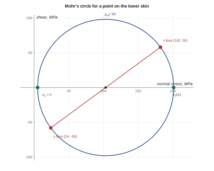
Mohr's circle draws these relations. Plot the stresses on the x face as one point and those on the y face as another, with opposite shear signs. The line joining them is a diameter; its center is the average normal stress and its radius is the maximum in-plane shear stress. The ends of the horizontal diameter are the principal stresses. Turning the element by \(\theta\) moves the points around the circle by \(2\theta\). The circle is quick to sketch, and it gives a feel for how a combination of tension and shear produces a larger principal stress than either alone.
Failure criteria for ductile metals
A material test gives a yield strength from a uniaxial tensile coupon. Real structure carries combined stresses, so a criterion is needed to compare the two. For ductile metals such as aluminum alloys and titanium, the von Mises criterion works well. It says yielding begins when the distortion energy reaches the value it has at yield in a tensile test, which gives an equivalent stress that can be compared directly with the yield strength.
The older Tresca criterion, based on the maximum shear stress, is slightly more conservative and easier to use by hand. For brittle materials and for composites, quite different criteria are needed, as Lesson 11 shows. Whatever criterion is used, the result is expressed in the aerospace industry as a margin of safety: the allowable divided by the applied stress (or load), minus one. A margin of zero means the part is exactly adequate; a negative margin means it fails the requirement. The factor of safety is already inside the applied ultimate load, so a margin of +0.10 means 10 percent of reserve beyond the requirement, not 10 percent beyond the expected service load.
Materials for airframes
Most of the Tern's structure, like that of most small and medium aircraft, is aluminum alloy. Two families dominate. The 2000-series alloys, with copper as the main alloying element, have good fatigue and crack growth resistance and are used where tension and fatigue govern, such as lower wing skins and fuselage skins. The 7000-series alloys, with zinc, are stronger and are used where compression and static strength govern, such as upper wing skins, stringers and spar caps. Titanium appears where heat, high strength in a small space, or contact with carbon fiber composites is involved. Composites, introduced in Lesson 11, are increasingly used for control surfaces, fairings and, on newer aircraft, primary structure.
# Plane stress at a point on the lower wing skin: principal stresses, Mohr's circle and margins of safety
import math
mats = {  # typical sheet values, MPa (A-basis allowables come from the approved data source, not from this table)
    "2024-T3 aluminum": (73100, 0.33, 324, 434),
    "7075-T6 aluminum": (71700, 0.33, 469, 538),
    "Ti-6Al-4V titanium": (113800, 0.34, 880, 950),
}
for k, (E, nu, Fty, Ftu) in mats.items():
    print(f"{k:20s} E = {E/1000:5.1f} GPa  nu = {nu}  yield {Fty} MPa  ultimate {Ftu} MPa")
sx, sy, txy = 182.0, 24.0, 58.0       # MPa at limit load: spanwise bending, chordwise, shear from torsion
c = (sx + sy) / 2; R = math.hypot((sx - sy) / 2, txy)
s1, s2 = c + R, c - R
theta = 0.5 * math.degrees(math.atan2(2 * txy, sx - sy))
vm = math.sqrt(sx**2 - sx * sy + sy**2 + 3 * txy**2)
print(f"\nMohr center {c:.1f} MPa, radius {R:.1f} MPa")
print(f"Principal stresses {s1:.1f} and {s2:.1f} MPa at {theta:.1f} deg from the span axis")
print(f"Maximum in-plane shear {R:.1f} MPa; von Mises stress {vm:.1f} MPa")
E, nu, Fty, Ftu = mats["2024-T3 aluminum"]
ex = (sx - nu * sy) / E; ey = (sy - nu * sx) / E; gxy = 2 * (1 + nu) * txy / E
print(f"Strains: ex = {ex*1e6:.0f}, ey = {ey*1e6:.0f}, gxy = {gxy*1e6:.0f} microstrain")
ms_yield = Fty / vm - 1                 # limit load against yield
ms_ult = Ftu / (1.5 * vm) - 1           # ultimate load (1.5 x limit) against ultimate strength
print(f"Margin of safety at limit (yield): {ms_yield:+.2f}")
print(f"Margin of safety at ultimate: {ms_ult:+.2f}")2024-T3 aluminum E = 73.1 GPa nu = 0.33 yield 324 MPa ultimate 434 MPa 7075-T6 aluminum E = 71.7 GPa nu = 0.33 yield 469 MPa ultimate 538 MPa Ti-6Al-4V titanium E = 113.8 GPa nu = 0.34 yield 880 MPa ultimate 950 MPa Mohr center 103.0 MPa, radius 98.0 MPa Principal stresses 201.0 and 5.0 MPa at 18.1 deg from the span axis Maximum in-plane shear 98.0 MPa; von Mises stress 198.6 MPa Strains: ex = 2381, ey = -493, gxy = 2111 microstrain Margin of safety at limit (yield): +0.63 Margin of safety at ultimate: +0.46
The point carries 182 MPa of spanwise tension, 24 MPa chordwise and 58 MPa of shear at limit load. The principal stress is 201 MPa, about 10 percent higher than the spanwise stress, and the von Mises stress is 199 MPa. Against the yield strength of 2024-T3 sheet that leaves a margin of +0.63 at limit load. At ultimate load, 1.5 times larger, the margin against the ultimate strength is +0.46. Both are positive, but Marcus reminds Arjun that this is a static check only: the lower skin is a fatigue-critical area, and Lesson 10 will show that fatigue, not static strength, usually sets its thickness.
The property values in the program are typical published figures, used here for teaching. Real design uses allowables from an approved source, such as the industry handbook of metallic material properties or the company's own qualified test data, chosen for the correct product form, thickness and grain direction. Using a value for thin sheet on a thick plate, or a longitudinal value for a part loaded across the grain, is a classic source of error that design reviews are set up to catch.
Thermal and residual stresses
Not all stresses come from external loads. Temperature changes cause materials to expand or contract, and where parts of different materials or different temperatures are joined, the mismatch causes thermal stresses. An aluminum skin bolted to a titanium fitting, or a wing exposed to sun on top and cold fuel below, develops such stresses. Manufacturing also leaves residual stresses: machining thick plate releases some, cold working fastener holes deliberately adds compressive ones that slow fatigue cracking. A complete stress analysis includes these effects where they matter, usually in joints and fittings.
Worked problem
Principal stresses in a spar web
A point in the front spar web near the root carries \(\sigma_x = 40\) MPa from bending and \(\tau_{xy} = 66\) MPa from shear, with \(\sigma_y = 0\). Find the principal stresses and the von Mises stress.
Show solution
- Center: \((40 + 0)/2 = 20\) MPa. Radius: \(\sqrt{20^2 + 66^2} = 69.0\) MPa.
- Principal stresses: \(\sigma_1 = 89.0\) MPa, \(\sigma_2 = -49.0\) MPa.
- Von Mises: \(\sqrt{40^2 + 3\times 66^2} = 120.9\) MPa.
Answer: Webs are dominated by shear, and pure shear produces equal and opposite principal stresses at 45 degrees. The compressive principal stress is why thin webs buckle in diagonal waves, a topic for Lesson 9.
Worked problem
Margin of safety in a fitting
A titanium fitting has an ultimate tensile allowable of 950 MPa. At ultimate load the von Mises stress is 780 MPa, and the company applies an additional fitting factor of 1.15 to joints. What is the margin of safety?
Show solution
- Applied stress including the fitting factor: \(780 \times 1.15 = 897\) MPa.
- Margin: \(950/897 - 1 = +0.06\).
Answer: A margin of +0.06 is acceptable but small. Fitting factors are added because joints carry concentrated loads and are hard to analyze precisely; many design standards require one.
Common mistakes
MistakeUsing a single uniaxial stress when the point also carries shear.
InsteadCombine the stresses with Mohr's circle or a failure criterion before comparing with an allowable.
MistakeComparing a limit-load stress with the ultimate strength.
InsteadCompare limit loads with yield and ultimate loads with ultimate strength, or apply the factor of safety consistently.
MistakeReading a margin of safety as the reserve over the service load.
InsteadThe factor of safety is already inside the ultimate load; the margin is reserve beyond the requirement.
MistakePicking an allowable for the wrong product form or grain direction.
InsteadUse values for the actual thickness, form and direction of the part, from an approved source.
Summary and key terms
- Plane stress describes most thin airframe parts, with three components at each point.
- Hooke's law links stress and strain through E, ν and G.
- Mohr's circle gives principal stresses and maximum shear.
- Ductile metals are checked with the von Mises equivalent stress, and results are reported as margins of safety.
- Equilibrium alone is not enough for indeterminate structures such as wing boxes, where stiffness and compatibility decide how loads share.
- Allowables must come from approved data for the right form and direction.
- Plane stress
- A state in which the stresses through the thickness are negligible.
- Principal stresses
- The largest and smallest normal stresses at a point, on planes with no shear.
- Mohr's circle
- A graphical construction showing how stress components change with orientation.
- Von Mises stress
- An equivalent stress for combined loading based on distortion energy.
- Margin of safety
- The allowable divided by the applied load or stress, minus one.
- Statically indeterminate
- A structure whose internal forces cannot be found from equilibrium alone.
- Allowable
- A design strength value from an approved, statistically based source.
Practice problems
Work each problem on paper first, then reveal the answer to check.
For E = 72 GPa and ν = 0.33, what is G?
Show answer
G = 72/(2 × 1.33) = 27.1 GPa.
Find the principal stresses for σx = 100 MPa, σy = 100 MPa, τ = 0.
Show answer
Both are 100 MPa; the circle shrinks to a point.
What is the von Mises stress in pure shear of 100 MPa?
Show answer
√3 × 100 = 173 MPa.
A part with an applied ultimate stress of 400 MPa has an allowable of 380 MPa. What is the margin?
Show answer
380/400 − 1 = −0.05, which fails.
In the program, double the shear stress. What happens to the yield margin?
Show answer
It falls sharply, because shear enters the von Mises stress multiplied by 3.
Why are lower wing skins usually 2000-series and upper skins 7000-series alloy?
Show answer
The lower skin is in tension and fatigue-critical; the upper skin is in compression and strength-critical.
Lesson quiz · 5 questions
Score 60% or more to complete this lesson.
Create a free account to save your progress, take quizzes and earn a certificate.