
AERO-310 · Lesson 3 of 12 · 24 min
Bending of open and closed thin-walled beams
A wing is a beam. It is long, it is fixed at one end to the fuselage, and the lift along its span bends it upward. A fuselage is a beam too, supported by the wing and loaded by its own weight, the payload and the tail. What makes aircraft beams special is that their cross-sections are thin-walled: a wing box is a hollow box of thin skins and spar webs, and a stringer is a thin strip bent into a Z or a hat. Their cross-sections are also rarely symmetric. This lesson extends the beam bending you know from MEC-200 to thin walls and unsymmetric sections, and applies it to the root of the Tern Block 2 wing box.
Assumptions of the engineering bending theory
Beam bending theory assumes that plane sections remain plane: a slice across the beam stays flat as the beam bends, so the axial strain varies linearly across the section. With a linear elastic material, the axial stress then varies linearly too. These assumptions are excellent for long, slender members away from points where load is applied and away from cutouts and sudden changes in section. Near the wing root, where the box meets the fuselage, and near large openings, they break down because of shear lag and restrained warping, effects that detailed finite element models capture. For most of the span they work well, and they are the backbone of preliminary sizing.
Thin walls add a further simplification. If the wall thickness \(t\) is small compared with the other dimensions, the stress can be taken as uniform through the thickness, and the section can be described by its midline: a set of lines with a thickness attached. Section properties then come from integrals along the midline rather than over an area. A wall segment of length \(L\) and thickness \(t\) contributes \(Lt\) to the area, and its second moment about an axis through its own center is negligible in the direction of its thickness.
Section properties
Three second moments of area describe how a section resists bending: \(I_{xx}\) about the horizontal axis, \(I_{yy}\) about the vertical axis, and the product of inertia \(I_{xy}\), all taken about axes through the centroid.
If the section has an axis of symmetry, \(I_{xy}\) is zero for axes aligned with it, and bending about one axis produces stress that varies only across the other. The familiar \(\sigma = My/I\) applies. Most aircraft sections lack that symmetry. A Z stringer, an angle, a wing box with spars of different heights or a cover thicker on top than below all have a non-zero product of inertia. A moment about one axis then makes the beam bend in both directions at once.
The general bending formula
For a section with moments \(M_x\) about the x axis and \(M_y\) about the y axis, and coordinates measured from the centroid, the direct stress at any point is
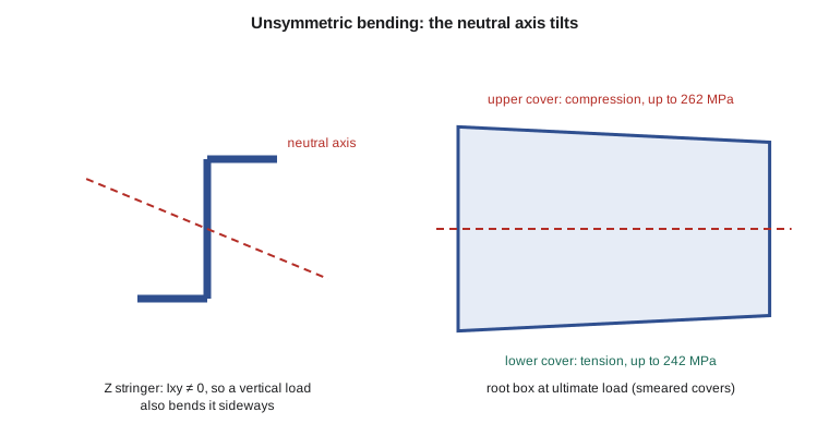
Sign conventions vary between textbooks; here a positive \(M_x\) puts material at positive \(y\) in tension. When \(I_{xy} = 0\) and \(M_y = 0\), the formula collapses to \(\sigma = M_x y/I_{xx}\). The neutral axis, where the stress is zero, is found by setting \(\sigma_z = 0\). For an unsymmetric section it is tilted, even when the moment acts about a horizontal axis.
An alternative is to find the principal axes of the section, the rotated axes for which the product of inertia vanishes, resolve the moment along them and use the simple formula twice. Both methods give the same stresses; the general formula is easier to program, and it is what most stress engineers use day to day.
Open and closed sections
For bending, it does not matter whether the section is open, like a channel or Z, or closed, like a box or tube: the direct stress depends only on the section properties, and the formula above applies to both. The difference appears in shear and torsion, where a closed section is dramatically stiffer and stronger, as Lessons 4 and 5 show. That is why aircraft wings use closed boxes and fuselages use closed shells. Open sections appear where access matters, such as in stringers, frames and the spar caps themselves.
In a real wing box, the covers are skins stiffened by stringers. For a first estimate, the stringer area can be smeared into the skin to give an equivalent thickness, so that the cover becomes a single thick wall. This smeared model gives the right bending stiffness and roughly the right stresses, but it hides the details of how the load is shared between skin and stringers. Lesson 6 replaces it with an idealization into booms, which keeps the stringers and spar caps as discrete areas.
# Unsymmetric bending of thin-walled sections built from straight wall segments
def props(segs):
    """segs: list of ((x1, y1), (x2, y2), t) in mm. Returns area, centroid and second moments."""
    A = Sx = Sy = 0.0
    for (x1, y1), (x2, y2), t in segs:
        L = ((x2 - x1) ** 2 + (y2 - y1) ** 2) ** 0.5
        a = L * t; A += a; Sx += a * (x1 + x2) / 2; Sy += a * (y1 + y2) / 2
    xc, yc = Sx / A, Sy / A
    Ixx = Iyy = Ixy = 0.0
    for (x1, y1), (x2, y2), t in segs:
        L = ((x2 - x1) ** 2 + (y2 - y1) ** 2) ** 0.5
        a = L * t
        X1, Y1, X2, Y2 = x1 - xc, y1 - yc, x2 - xc, y2 - yc
        Ixx += a * (Y1 * Y1 + Y1 * Y2 + Y2 * Y2) / 3
        Iyy += a * (X1 * X1 + X1 * X2 + X2 * X2) / 3
        Ixy += a * (2 * X1 * Y1 + X1 * Y2 + X2 * Y1 + 2 * X2 * Y2) / 6
    return A, xc, yc, Ixx, Iyy, Ixy
def sigma(Mx, My, x, y, Ixx, Iyy, Ixy):
    """Direct stress; positive Mx puts material at positive y in tension."""
    D = Ixx * Iyy - Ixy ** 2
    return ((My * Ixx - Mx * Ixy) / D) * x + ((Mx * Iyy - My * Ixy) / D) * y
# 1. A Z-section stringer: flanges 20 mm, web 40 mm, all 2 mm thick
z = [((20, 20), (0, 20), 2), ((0, 20), (0, -20), 2), ((0, -20), (-20, -20), 2)]
A, xc, yc, Ixx, Iyy, Ixy = props(z)
print(f"Z stringer: A = {A:.0f} mm2, Ixx = {Ixx:.0f}, Iyy = {Iyy:.0f}, Ixy = {Ixy:.0f} mm4")
Mx = 50e3  # N mm about the horizontal axis
for pt in ((20, 20), (-20, -20), (0, 20)):
    print(f"   point {pt}: stress {sigma(Mx, 0, pt[0]-xc, pt[1]-yc, Ixx, Iyy, Ixy):7.1f} MPa (Mx = 50 N m)")
# 2. Tern Block 2 root wing box: 1020 mm wide, front spar 304 mm deep, rear spar 258 mm deep
fs, rs, w = 304.0, 258.0, 1020.0
tc, tw = 6.0, 3.0   # smeared cover (skin + stringers) and spar web thickness, mm
box = [((0, fs / 2), (w, rs / 2), tc), ((w, rs / 2), (w, -rs / 2), tw),
       ((w, -rs / 2), (0, -fs / 2), tc), ((0, -fs / 2), (0, fs / 2), tw)]
A, xc, yc, Ixx, Iyy, Ixy = props(box)
print(f"\nRoot box: A = {A:.0f} mm2, centroid x = {xc:.0f} mm aft of front spar")
print(f"Ixx = {Ixx/1e6:.1f}e6, Iyy = {Iyy/1e6:.1f}e6, Ixy = {Ixy/1e6:.2f}e6 mm4")
Mx, My = -420.7e6, 30e6     # ultimate: lift bending (upper covers in compression), small drag moment
for lab, pt in (("front spar top", (0, fs / 2)), ("rear spar top", (w, rs / 2)),
                ("front spar bottom", (0, -fs / 2)), ("rear spar bottom", (w, -rs / 2))):
    s = sigma(Mx, My, pt[0] - xc, pt[1] - yc, Ixx, Iyy, Ixy)
print(f" {lab:18s} {s:7.1f} MPa")Z stringer: A = 160 mm2, Ixx = 42667, Iyy = 10667, Ixy = 16000 mm4 point (20, 20): stress -26.8 MPa (Mx = 50 N m) point (-20, -20): stress 26.8 MPa (Mx = 50 N m) point (0, 20): stress 53.6 MPa (Mx = 50 N m) Root box: A = 13929 mm2, centroid x = 505 mm aft of front spar Ixx = 253.5e6, Iyy = 1499.7e6, Ixy = 0.00e6 mm4 front spar top -262.3 MPa rear spar top -203.7 MPa front spar bottom 242.1 MPa rear spar bottom 224.4 MPa
The Z stringer shows the effect clearly. A moment of 50 N m about the horizontal axis produces stresses that are not simply proportional to the height: the outer tips of the flanges, at the same distance from the centroid as the web ends, carry only half the stress and with the opposite sign. If the stringer is free to bend sideways it will do so; in a wing cover, the skin restrains it, which is one reason Z stringers work well when attached to skin but poorly on their own.
The root box, 1020 mm wide with spars 304 mm and 258 mm deep, and smeared covers 6 mm thick, has a second moment of area of about 254 × 10⁶ mm⁴ about its horizontal axis. Because the model is symmetric about the chord line, its product of inertia is zero. The ultimate root moment of 421 kN m gives a compressive stress of 262 MPa at the top of the front spar, where the box is deepest, and 204 MPa at the top of the rear spar. The small drag moment of 30 kN m adds a few megapascals of difference between front and rear. These stresses are within the strength of 7075-T6, but compression in thin skins brings buckling into play, which Lessons 8 and 9 address.
How deep a box, and where to put the material
The bending formula shows why a structural designer wants the wing to be thick. For a box whose covers carry most of the bending, \(I \approx 2At(h/2)^2\), so the stress for a given moment falls with the square of the depth if the cover area is fixed, or the area needed falls linearly with depth. The aerodynamicists want thin sections for low drag at high speed; the structures team wants thick ones for light weight. The Tern's 15 percent thick root section is a compromise that suits a slow commuter aircraft. A high-speed business jet, with thinner sections, pays for its speed in wing weight.
The same formula shows why material should sit as far from the neutral axis as possible. Spar caps and stringers concentrate area at the top and bottom of the box, where it does the most good. Material near the middle of the spar webs contributes little to bending; it is there to carry shear. Good wing box design follows that division of labor: covers and caps for bending, webs for shear, and the closed box for torsion.
Worked problem
Stress in a symmetric box
A rectangular wing box is 800 mm wide and 240 mm deep, with covers 5 mm thick and webs 3 mm thick. Find \(I_{xx}\) and the cover stress for a bending moment of 200 kN m.
Show solution
- Covers: \(2 \times 800 \times 5 \times 120^2 = 115.2 \times 10^6\) mm⁴.
- Webs: \(2 \times 3 \times 240^3/12 = 6.9 \times 10^6\) mm⁴.
- \(I_{xx} = 122.1 \times 10^6\) mm⁴.
- Cover stress: \(\sigma = 200 \times 10^6 \times 120/122.1 \times 10^6 = 197\) MPa.
Answer: The covers supply 94 percent of the bending stiffness. Thin-wall approximations that keep only the covers are common for quick estimates.
Worked problem
Neutral axis of a Z stringer
For the Z stringer in the program, \(I_{xx} = 42\,667\), \(I_{yy} = 10\,667\) and \(I_{xy} = 16\,000\) mm⁴. Find the angle of the neutral axis for a moment \(M_x\) alone.
Show solution
- With \(M_y = 0\): \(\tan\alpha = -M_x I_{xy}/(M_x I_{yy}) = -I_{xy}/I_{yy} = -16\,000/10\,667 = -1.5\).
- So \(\alpha = -56.3^\circ\) from the x axis.
Answer: The neutral axis is steeply tilted. A load applied to this stringer alone would make it bend sideways almost as much as vertically, unless something restrains it.
Common mistakes
MistakeUsing σ = My/I for an unsymmetric section.
InsteadInclude the product of inertia, or work in principal axes.
MistakeMeasuring coordinates from an edge instead of the centroid.
InsteadSection properties and the bending formula assume centroidal axes.
MistakeApplying beam theory right at the wing root joint or next to a large cutout.
InsteadPlane sections do not stay plane there; use refined analysis for those regions.
MistakeThinking that a closed section bends differently from an open one.
InsteadBending stress depends on section properties only; closure matters for shear and torsion.
Summary and key terms
- Thin-walled beam theory assumes plane sections stay plane and stress is uniform through the wall.
- Section properties come from integrals along the midline.
- Unsymmetric sections have a non-zero product of inertia, so the general bending formula is needed and the neutral axis tilts.
- Bending stress depends only on section properties, so open and closed sections behave alike in bending.
- For the Tern root box at ultimate load, compressive cover stresses reach about 262 MPa.
- Depth is the most powerful way to reduce bending stress, which sets up the trade between aerodynamic thinness and structural weight.
- Product of inertia
- The integral of xy over the section; zero for a symmetric section about its axes.
- Neutral axis
- The line in a bent section where the direct stress is zero.
- Principal axes
- The pair of centroidal axes for which the product of inertia is zero.
- Smeared thickness
- An equivalent wall thickness that includes stringer area spread over the skin.
- Shear lag
- The departure from plane-section behavior when shear deformation of thin walls matters.
- Thin-walled section
- A section whose wall thickness is small compared with its other dimensions.
Practice problems
Work each problem on paper first, then reveal the answer to check.
A thin tube has radius 100 mm and wall 2 mm. What is its I about a diameter?
Show answer
I = πr³t = π × 10⁶ × 2 = 6.28 × 10⁶ mm⁴.
Doubling the depth of a box whose covers carry the bending changes the cover stress how?
Show answer
It halves it for the same cover area, since I grows with h² and stress with M h/(2I).
What is I_xy for an equal-flange channel about its centroidal axes?
Show answer
Zero, because the channel is symmetric about its horizontal axis.
In the program, make the rear spar 304 mm deep too. What changes?
Show answer
The box becomes rectangular; front and rear top stresses become equal.
Why do stringers sit at the top and bottom of a wing box rather than in the webs?
Show answer
Area far from the neutral axis adds most to I.
State one place where the engineering bending theory is unreliable.
Show answer
At the wing-fuselage joint, near large cutouts or where loads are concentrated.
Lesson quiz · 5 questions
Score 60% or more to complete this lesson.
Create a free account to save your progress, take quizzes and earn a certificate.