
WLD-220 · Lesson 7 of 12 · 16 min
Groove weld symbols
Groove welds are where welding symbols carry the most information and where misreading them does the most harm. A groove weld symbol says what shape to prepare the edges to, which member to prepare, how deep to bevel, how much of the joint the weld must penetrate, what root opening and groove angle to fit up to, whether there is backing, a spacer or a back weld, and how the face is to be finished. On the Riverside girder splices and the Coldwater lifting lugs, a groove weld symbol misread is a weld cut out, a joint re-prepared and a test repeated. This lesson goes through the groove weld symbols and their dimensions, the critical difference between complete and partial joint penetration on the symbol, and the symbols for back welds, backing and melt-through.
The groove weld symbols
Each groove shape has its own weld symbol, drawn on the reference line, below it for the arrow side and above for the other side. The symbols are drawn to look like the cross-section of the groove.
| Groove | Symbol | Notes |
|---|---|---|
| Square | Two short parallel lines across the reference line | Edges left square, with or without a root opening |
| V | A V | Both members bevelled |
| Bevel | A vertical line with a slanted line, like half a V | One member bevelled; the vertical stroke is always on the left |
| U | A U shape | Both members prepared with a radius at the bottom |
| J | A vertical line with a curved line, like half a U | One member prepared; the vertical stroke is always on the left |
| Flare-V | Two curved lines back to back | Groove between two rounded surfaces |
| Flare-bevel | A vertical line with one curved line | Groove between a rounded surface and a flat one |
Symbols on both sides of the reference line mean grooves from both sides: a V above and below is a double-V groove, a bevel above and below a double-bevel. The two sides can be different shapes or sizes: a deeper bevel on one side than the other is common on thick plate to balance the welding.
For bevel and J grooves, the vertical stroke is always drawn on the left, just as with the fillet triangle, and it has nothing to do with which member is bevelled. The member to be prepared is shown by the break in the arrow, as the lesson on the reference line explained. If the arrow is not broken, the drafter is saying either member can be prepared.
Groove dimensions and where they go
Each groove dimension has its own location on the symbol:
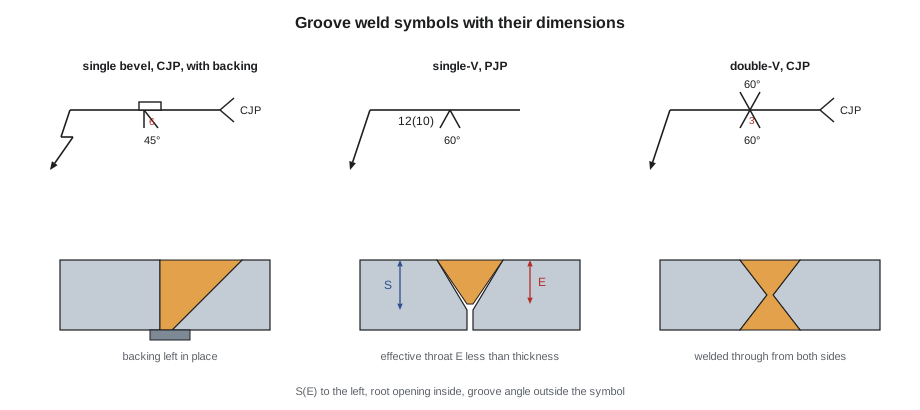
- Depth of bevel, S, is written to the left of the weld symbol. It is the depth of the preparation from the surface.
- Groove weld size, E, is written in parentheses after the depth of bevel, also to the left of the symbol: S(E). It is the depth of the weld's effective throat, the depth into the joint that the weld is designed to fuse.
- Root opening is written inside the weld symbol, between its arms or in the space at its base.
- Groove angle is written outside the symbol, above it when the symbol is above the line and below it when the symbol is below the line.
- Groove radius and root face for U and J grooves are usually shown in a detail or section rather than on the symbol.
- Length, if the groove weld is not full length, goes to the right of the symbol, as for fillets.
Complete joint penetration on the symbol
How does a symbol say that a groove weld is complete joint penetration? There are several ways, and drawings use them in combination:
- A single-sided groove symbol with no depth of bevel and no groove weld size, on a joint where the preparation goes through the full thickness, means CJP.
- A double-sided groove symbol with no dimensions on either side means CJP, with the depth of each preparation shown in a detail or left to the procedure.
- The letters CJP in the tail make it explicit, and many specifications require them.
- A groove weld size, E, equal to the plate thickness, for example 20(20) (3/4(3/4)) on 20 mm (3/4 in) plate, also means CJP.
Partial joint penetration is shown by giving a groove weld size smaller than the thickness, for example 12(10) (1/2(3/8)) on thicker plate: bevel 12 mm (1/2 in) deep, weld designed to an effective throat of 10 mm (3/8 in). A PJP groove symbol should always carry its dimensions. A groove symbol without dimensions where the intent is not obvious is a question for the detailer, not a guess.
The reason the effective throat can be less than the depth of bevel is that the arc may not fuse right to the bottom of a narrow, sharp groove. The codes allow for this: depending on the process, the position and the groove angle, a prequalified PJP weld may be credited with the full depth of bevel, or with the depth less a small allowance, often 3 mm (1/8 in). The detailer works out S from the E the engineer requires, and the fitter prepares S.
Calculating effective throat
Lucia makes Devon work through what a groove symbol means numerically before he lays out a joint, because the numbers are what the inspector will check. For a CJP weld, the effective throat is the thickness of the thinner part joined. For a PJP weld, it is the groove weld size, which is the depth of bevel or the depth less the allowance, and on a double-sided PJP the two sides add up.
# Effective throat for CJP and PJP groove welds from the symbol (illustrative allowance rules)
def throat(kind, t, s_list, allow):
    # kind: "CJP" or "PJP"; t: thinner plate; s_list: depth of bevel on each welded side
    if kind == "CJP":
        return t
    return sum(max(s - allow, 0) for s in s_list)
cases = [  # name, kind, thickness, depths of bevel, allowance per side (mm)
    ("lifting lug, single bevel", "CJP", 25, [25], 0),
    ("base plate, single-V PJP, 60 deg", "PJP", 20, [12], 0),
    ("base plate, single bevel PJP, 45 deg", "PJP", 20, [12], 3),
    ("thick splice, double-bevel PJP", "PJP", 40, [16, 16], 3),
]
for name, kind, t, s_list, allow in cases:
    e = throat(kind, t, s_list, allow)
print(f"{name:38} {kind}: effective throat {e:.0f} mm of {t} mm ({100 * e / t:.0f}% of thickness)")lifting lug, single bevel CJP: effective throat 25 mm of 25 mm (100% of thickness) base plate, single-V PJP, 60 deg PJP: effective throat 12 mm of 20 mm (60% of thickness) base plate, single bevel PJP, 45 deg PJP: effective throat 9 mm of 20 mm (45% of thickness) thick splice, double-bevel PJP PJP: effective throat 26 mm of 40 mm (65% of thickness)
The allowances in this program are illustrative. The actual rule for a prequalified PJP weld depends on the process, the position and the groove angle, and is given in the code tables. The point of the calculation is the same either way: a 45 degree bevel prepared to the depth on the symbol may be credited with less throat than the depth, and a fitter who prepares less depth than shown takes away throat the design is relying on.
Back welds and backing welds
A back weld or backing weld is a weld on the other side of a groove weld, shown with a small half-circle symbol on the opposite side of the reference line from the groove symbol. The two are told apart by sequence:
- A back weld is made after the groove weld, on the root side, often after back gouging. The symbol may be on a second reference line, or the tail may say back gouge, or the order of operations may be written in a note.
- A backing weld is made before the groove weld, on the root side, to act as backing for it. It is shown on the first reference line, nearest the arrow, with the groove on a second line.
On a double-V joint, there is no back weld symbol: the second side is a groove weld of its own, shown by its own V. If the second side must be back-gouged before welding, the tail or a note says so.
Backing, spacers and melt-through
Single-sided groove welds need something under the root, and the symbol shows what.
- A backing symbol, a small rectangle on the other side of the reference line from the groove symbol, means a backing strip is used. The letter R inside it means the backing is to be removed after welding. The material and size of the backing are given in the tail or a note.
- A spacer symbol, a small rectangle drawn across the reference line within the groove symbol, means a spacer is placed in the root of a double-sided joint. It is removed by back gouging.
- A melt-through symbol, a small filled half-circle on the other side of the line, means the root pass must show visible penetration on the back side, as in an open-root weld. A height may be given.
- A consumable insert symbol, a small square on the other side, means a consumable insert ring or strip is placed in the root, common on pipe welded with GTAW.
The lifting lug joints on the Coldwater base frame are single-bevel CJP grooves with steel backing on the back of the lug. The backing symbol sits above the line, opposite the bevel symbol below it, and the tail gives the backing as a 6 x 25 (1/4 x 1) flat bar of the same grade as the lug. Because the backing is left in place, it must be continuous for the full length of the joint and fused by the root pass. Note 10 on the drawing says the backing may stay on these joints because they carry static load.
Contour and finish on groove welds
A groove weld may be required flush or with its reinforcement removed, for example where another piece sits on top, where the weld will be ultrasonically tested and reinforcement would interfere, or on a fatigue-loaded joint where the reinforcement is a stress raiser. The contour symbol, a line or curve drawn beside the groove symbol, says what shape the face must be, and a letter beside it says how to get there, such as G for grinding. Under the current edition of AWS A2.4, a flush symbol is used for groove welds that must be level with the surface, and the flat symbol is kept for fillets. The details are in the lesson on supplementary symbols.
On the Riverside girder flange splices, every symbol carries the flush contour with G, and the specification requires the grinding to run in the direction of stress. The welds are then ultrasonically tested over their full length.
Reading two groove symbols
Devon writes out two symbols from the base frame package the way Lucia taught him.
- Lifting lug to beam flange: bevel symbol below the line, broken arrow to the lug, CJP in the tail, root opening 6 inside the symbol, 45 degrees below it, backing symbol above the line, tail WPDS-31. In words: prepare a 45 degree bevel on the lug through its full 25 mm thickness, fit to a 6 mm root opening over continuous backing on the far side, and weld complete joint penetration to data sheet 31.
- Base plate to post: bevel symbol below the line, 12(9) to the left, 45 degrees below, fillet stacked on top with 8 to its left, weld-all-around circle, tail WPDS-22. In words: bevel the post 12 mm deep at 45 degrees all around, weld to an effective throat of 9 mm, then add an 8 mm reinforcing fillet all around, to data sheet 22.
Common mistakes
MistakeTreating a groove symbol without dimensions as optional depth.
InsteadSingle-sided groove symbols without dimensions normally mean CJP; check the tail and the notes.
MistakePreparing less depth of bevel than shown on a PJP symbol.
InsteadThe effective throat depends on the depth; prepare at least the depth shown.
MistakeConfusing the groove angle with the bevel angle on a V.
InsteadThe angle on a V symbol is the included angle; each side is half.
MistakeLeaving a backing bar off because the root looks good from the face.
InsteadThe backing symbol is part of the joint design; fit it continuous as shown.
MistakeGrinding a weld flush when the symbol only shows a convex contour.
InsteadFinish only as the contour and finish symbols call for.
Summary and key terms
- Groove symbols look like the groove cross-section: square, V, bevel, U, J, flare-V and flare-bevel.
- Bevel and J symbols always have the vertical stroke on the left; the broken arrow shows the member to prepare.
- Depth of bevel and groove weld size go to the left as S(E); root opening inside; groove angle outside.
- Single-sided grooves without dimensions, CJP in the tail, or E equal to the thickness indicate complete joint penetration.
- PJP welds carry a groove weld size smaller than the thickness, and the code may credit less throat than the depth of bevel.
- Back weld, backing, spacer, melt-through and insert symbols show what happens at the root.
- Depth of bevel (S)
- The depth of the edge preparation from the surface.
- Groove weld size (E)
- The effective throat of a groove weld, the depth it is designed to fuse.
- Back weld
- A weld made on the root side of a groove weld after the groove weld.
- Backing weld
- A weld made on the root side before the groove weld, to serve as backing.
- Backing
- Material placed at the root of a joint to support the molten weld metal.
- Melt-through
- Visible root reinforcement produced through a joint welded from one side.
Practice problems
Work each problem on paper first, then reveal the answer to check.
A bevel symbol reads 16(13) to its left. What do the two numbers mean?
Show answer
Bevel 16 mm deep; weld to an effective throat of 13 mm.
A V symbol has 3 inside and 60 degrees below it. What do they mean?
Show answer
A 3 mm root opening and a 60 degree included groove angle.
What does R inside a backing symbol mean?
Show answer
Remove the backing after welding.
Lesson quiz · 5 questions
Score 60% or more to complete this lesson.
Create a free account to save your progress, take quizzes and earn a certificate.