
WLD-220 · Lesson 10 of 12 · 17 min
NDE symbols and inspection information
A weld that has been made has not yet been accepted. Between the welder lifting the hood and the piece leaving the shop, the weld may be visually inspected, measured, tested with dye penetrant or magnetic particles, ultrasonically scanned or radiographed, and the results recorded against its number on the weld map. The drawing and the specification say which of these happens to which weld and how much. Some of this is carried on the welding symbol itself, by examination symbols that use the same reference line and arrow as welding symbols; most is in the general notes, the weld map and the inspection and test plan. This lesson covers the nondestructive examination symbols, how inspection requirements are shown on drawings, how welds are identified so that their records can be traced, and what hold points mean for a welder's day.
Nondestructive examination
Nondestructive examination, NDE, also called nondestructive testing, NDT, looks for defects in a weld without damaging it. Each method finds different kinds of defects.
| Letters | Method | What it finds |
|---|---|---|
| VT | Visual testing | Surface defects, size, profile, undercut, cracks visible at the surface |
| PT | Penetrant testing | Surface-breaking cracks and porosity, on any non-porous metal |
| MT | Magnetic particle testing | Surface and near-surface cracks in magnetic steels |
| UT | Ultrasonic testing | Internal defects such as lack of fusion, cracks and slag, and thickness |
| RT | Radiographic testing | Internal volumetric defects such as porosity and slag, and some planar defects |
| ET | Electromagnetic testing | Surface defects in conductive materials |
| LT | Leak testing | Leaks in sealed or pressure-containing welds |
| PRT | Proof testing | Load or pressure capacity of the finished part |
| AET | Acoustic emission testing | Active defects during loading |
Visual inspection is applied to every weld, on every job, and is the cheapest and most effective method there is. Most welds that are rejected are rejected for reasons a careful welder could have seen first. The other methods are applied to a selected proportion of welds, or to all welds of a certain kind, as the code, the specification and the drawing require.
The examination symbol
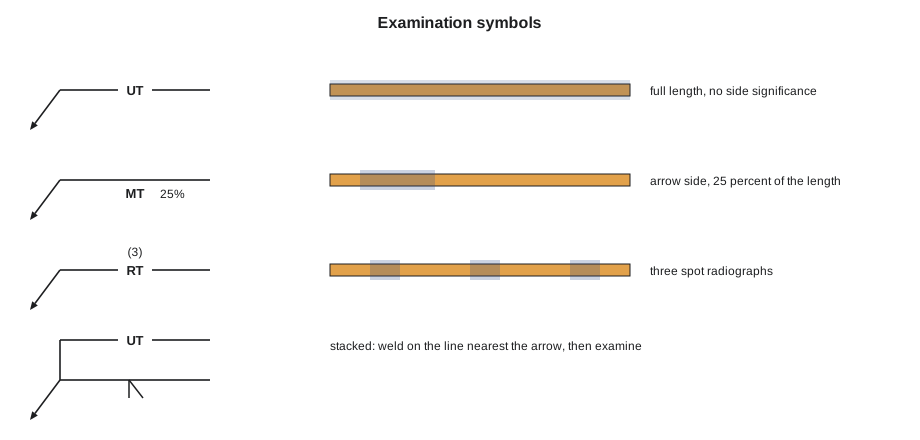
An examination symbol uses the same reference line, arrow and tail as a welding symbol, but instead of a weld symbol it carries the letters of the examination method.
- Letters below the reference line mean examine the arrow side; above the line, the other side; on both sides, both sides.
- Letters centred on the reference line mean the examination has no side significance, such as radiography or ultrasonic testing of a whole joint.
- Several methods can be shown together, such as MT and UT, joined by a plus sign or stacked.
- The length to be examined goes to the right of the letters. If no length is given, the full length of the joint is examined.
- A percentage to the right means that proportion of the length is to be examined, with the location of the sections left to the inspector or set out in the specification.
- The number of examinations, such as spot radiographs, goes in parentheses above or below the letters.
- The examine-all-around circle and the field flag go at the junction of the arrow and reference line, as on a welding symbol.
- The tail can hold the procedure or standard for the examination, and the acceptance criteria.
For radiography, a separate radiation direction symbol, a small sun-like symbol with an angle, can show the direction of the beam. An examination symbol can be shown on its own, or combined with the welding symbol on a separate reference line further from the arrow, meaning weld first and then examine.
Where inspection requirements usually live
On structural shop drawings, examination symbols are used mainly where a particular weld needs testing beyond the normal requirements. Most inspection requirements come from three other places:
- The code, which sets the minimum inspection for each kind of weld and the acceptance criteria for each method. Visual inspection of every weld is required by the structural codes, and certain welds, such as CJP welds in tension or in cyclically loaded members, may require ultrasonic or radiographic testing.
- The project specification, which may increase the amount of testing, name the standards and the qualifications of the technicians, and set who does the testing, such as the fabricator's inspector or the owner's independent inspector.
- The general notes, which repeat the requirements that apply to this drawing, such as all CJP welds 100 percent UT, 10 percent of fillet welds by MT.
In Canada, structural fabricators certified to CSA W47.1 must have a welding inspection system, and visual inspection is carried out by inspectors certified to CSA W178.2. NDE technicians are certified under the Canadian General Standards Board scheme, CAN/CGSB-48.9712, administered by Natural Resources Canada. Hartwell's inspector, Lucia Ferreira, holds a CSA W178.2 Level 2 certification.
Weld identification and weld maps
When a weld is tested and a defect is found, everyone needs to know exactly which weld it was, who made it, with which procedure and which batch of filler, and when. That is impossible unless every weld has an identity. The weld map does this. It is a copy of the assembly drawing, or a separate sheet, on which every weld is given a number, and a weld log records the details of each one.
- Each weld number appears on the drawing next to its symbol, or in a bubble with a leader to the joint.
- The weld log records for each weld number: the welding procedure, the welder's identification, the date, the filler lot, the preheat and interpass checks if required, and the inspection results.
- The welder marks the weld with a stamp or paint marker, near the weld, with the weld number or the welder's identification, as the specification requires. On some work, such as fracture-critical bridge members, stamping is not allowed and paint marking or photographs are used.
- Repairs get their own number, often the original number with a suffix such as R1, so that the history is kept.
On the Coldwater base frame, Raj's weld map numbers each weld from W1 to W38, grouped by type. The four lifting lug CJP welds are W1 to W4; the gusset fillets are W11 to W26; the end plate welds are W5 to W10. Each one has a line in the weld log that Devon fills in as he works.
# Choose welds for partial NDE from the weld map, reproducibly, and total the length to be tested
import random
welds = {  # weld number: (type, length mm)
    "W1": ("CJP", 250), "W2": ("CJP", 250), "W3": ("CJP", 250), "W4": ("CJP", 250),
    **{f"W{n}": ("fillet", 300) for n in range(11, 27)},
    **{f"W{n}": ("fillet", 450) for n in range(5, 11)},
}
rules = {"CJP": ("UT", 1.00), "fillet": ("MT", 0.10)}   # method and fraction of welds, from the general notes
rng = random.Random(204)    # seed recorded on the inspection plan so the selection can be repeated
for kind, (method, frac) in rules.items():
    pool = sorted(w for w, (t, _) in welds.items() if t == kind)
    n = max(1, round(frac * len(pool) + 0.499)) if frac < 1 else len(pool)
    chosen = sorted(rng.sample(pool, n), key=lambda w: int(w[1:]))
    length = sum(welds[w][1] for w in chosen)
    print(f"{method} on {kind}: {n} of {len(pool)} welds -> {', '.join(chosen)}")
print(f" length to examine: {length} mm")UT on CJP: 4 of 4 welds -> W1, W2, W3, W4 length to examine: 1000 mm MT on fillet: 3 of 22 welds -> W20, W23, W25 length to examine: 900 mm
Partial testing works only if the welder does not know in advance which welds will be tested, and only if the inspector is free to choose more when defects are found. Codes and specifications usually say that when a partial test finds a rejectable defect, more welds by the same welder or of the same kind must be tested, often two more for each one rejected, and if those fail, all of them. A welder whose work is sampled and found good is protecting the whole batch.
Inspection and test plans and hold points
An inspection and test plan, ITP, lists every inspection and test activity on a job in order, with the document that governs it, who does it, and what kind of point it is.
- A hold point is a step that must not be passed until the named inspector has checked it and released it. Work stops until then.
- A witness point is a step the inspector must be told about in advance and may choose to watch; work can go ahead if they do not come.
- A review point is a document review, such as checking mill certificates or welder qualifications.
For a welder, hold points are the ones that matter most, because they stop the work. Typical hold points on structural and pressure work are fit-up of CJP joints before welding, after back gouging before the second side is welded, after the root pass on some pipe joints, after a repair excavation before re-welding, and before painting or before final assembly that would hide the weld. The welding symbol does not show hold points. The ITP and sometimes the general notes do.
On the Coldwater base frame ITP, there are three hold points for the shop: fit-up of each lifting lug CJP joint before welding, the backing fit-up on the same joints, and final visual inspection before blast and paint. Devon tags each lug joint with a yellow hold tag when it is fitted and calls Lucia. She checks the bevel angle, root face, root opening and the backing, signs the tag and the ITP, and only then does he weld.
What the welder checks
The welder is the first inspector of every weld. Hartwell's welders check and record, before the inspector sees the weld:
- That the joint matches the drawing and the procedure before welding: preparation, fit-up, cleanliness and preheat.
- That each pass is clean and sound before the next, including interpass temperature where it is controlled.
- That the finished weld is the size and length shown, using fillet gauges and a rule.
- That there are no cracks, undercut beyond the limits, overlap, porosity, unfilled craters or arc strikes.
- That the weld is marked and the log is filled in.
Lucia's view is that her job is to confirm the welder's inspection, not to do it for them.
What happens when a test finds a defect
Two weeks after the base frame ships, the ultrasonic technician finds an indication in a lug weld on another skid built the same month. Devon watches what follows, because one day it will be his weld. The technician reports the indication, its location along the weld and its depth below the surface, and compares it with the acceptance criteria in the code for that kind of joint and loading. It is over the limit. The weld is marked as rejected on the weld map and the weld log, and a nonconformance report is opened.
Lucia checks the log for that weld number: welder, procedure, wire lot, preheat readings and the fit-up record. The fit-up sheet shows a root opening at the bottom of the tolerance, and the indication is at the root, which points to lack of fusion at a tight root rather than a problem with the welder's technique on the fill passes. Elena, the welding engineer, writes a repair procedure: gouge out the defect from the face side to sound metal, confirm by magnetic particle testing that the excavation is clean, preheat, reweld to the original procedure, and retest by ultrasonic testing after the required delay.
Because the specification calls for more testing when partial tests fail, Lucia also selects additional welds by the same welder on the same job for testing. They pass. The repair is given its own number, the original number with R1, and the repair, the excavation check and the retest are all recorded against it. The nonconformance report is closed with a note to the fitting crew about holding the root opening near the middle of its tolerance on those lugs.
Devon takes two lessons from it. The record is what made the cause easy to find. And a fit-up dimension that was technically inside the tolerance still mattered, because it was at the edge.
Common mistakes
MistakeTreating NDE letters centred on the line as arrow side only.
InsteadCentred letters have no side significance; the whole joint is examined.
MistakeWelding through a hold point because the inspector is busy.
InsteadA hold point stops the work until the named inspector releases it.
MistakeLeaving the weld log for the end of the day.
InsteadRecord each weld as it is made, with procedure, filler lot and checks.
MistakeAssuming welds not marked for NDE will not be inspected.
InsteadEvery weld gets visual inspection, and partial testing can select any weld.
MistakeGrinding a defect out and re-welding without telling anyone.
InsteadRepairs are recorded and inspected as repairs, with their own identification.
Summary and key terms
- Examination symbols use the reference line, arrow and tail like welding symbols, with method letters in place of a weld symbol.
- Below the line is arrow side, above is other side, centred has no side significance.
- Length or percentage goes to the right; the number of examinations in parentheses.
- Most inspection requirements come from the code, the specification and the general notes.
- Weld maps and weld logs give every weld an identity and a record.
- Hold points in the inspection and test plan stop work until the inspector releases them.
- NDE
- Nondestructive examination, testing that does not damage the part.
- Examination symbol
- A symbol on a reference line showing the method and extent of an examination.
- Weld map
- A drawing on which each weld is given an identifying number.
- Weld log
- A record of the procedure, welder, filler, checks and results for each weld.
- Hold point
- A step in an inspection and test plan that cannot be passed without the inspector releasing it.
- Inspection and test plan
- A list of inspection activities, governing documents, responsibilities and hold points for a job.
Practice problems
Work each problem on paper first, then reveal the answer to check.
An examination symbol reads UT centred on the line with no length. What does it require?
Show answer
Ultrasonic testing of the whole joint, with no side significance.
A symbol has MT below the line and 25% to the right. What does it require?
Show answer
Magnetic particle testing on the arrow side of 25 percent of the weld length.
What is the difference between a hold point and a witness point?
Show answer
Work stops at a hold point until released; at a witness point the inspector may watch but work can proceed.
Lesson quiz · 5 questions
Score 60% or more to complete this lesson.
Create a free account to save your progress, take quizzes and earn a certificate.