
WLD-220 · Lesson 12 of 12 · 17 min
Capstone: from drawing to fit-up on a skid base frame
Everything in this course comes together in one job. Glen Teskey hands Devon Okafor the controlled package for the Coldwater separator skid base frame, assembly B1, sheets SK-201 to SK-211, now at the revisions on the register, and tells him the frame is his: read the drawings, plan the cutting and fit-up, fit the frame, check it, call the inspector at the hold points, and have it ready to weld by Friday. Marta Kowalchuk will check his work at each stage. Lucia Ferreira will inspect at the hold points. Raj Bhullar is upstairs if anything on the drawings does not make sense. This lesson follows the job from the sleeve of drawings to a fitted frame released for welding, and uses each skill from the course along the way.
Step 1: check the package
Devon starts where the first lesson said to start: with the paper. He checks every sheet against the drawing register, including SK-206 at revision D, issued after his question in the supplementary symbols lesson. He reads each title block for scale and units, each revision block for what changed, and the general notes on SK-204 that apply to all the frame sheets. He writes the key notes on a card he keeps in his shirt pocket:
- Welding to the code named in note 3, by the procedures referenced in the symbol tails and the weld map.
- All fillet welds not otherwise sized are 6 mm; gusset fillets wrap the ends for 12 mm (1/2 in).
- All CJP welds 100 percent UT; 10 percent of fillets by MT, selected by the inspector.
- Hold points: lug fit-up, lug backing, final visual.
- Tolerances not otherwise noted from note 9; overall frame length and width to ±3 mm (±1/8 in); diagonals equal within 5 mm (3/16 in).
- Faying surfaces of the vessel saddle connection not to be painted.
He finds the pieces on the bill of materials and checks them against what is on the cart from the cutting table: two long beams b1 and b2, four cross members b3 to b6, two end plates, eight gussets p7, four lifting lugs p11 to p14, the drain pan and the saddle pads. One cross member is marked b5 on both ends; the other is marked b5 at one end and b6 at the other. He measures both, finds that the one marked b5 twice is b5 and that b6 has a set of holes b5 lacks, and re-marks it.
Step 2: read every weld
With the pieces sorted, Devon goes through the weld map, W1 to W38, and reads each symbol out loud to Marta. The welds fall into four groups.
| Welds | Joint | Symbol, read out |
|---|---|---|
| W1 to W4 | Lifting lug to beam top flange | Bevel on the lug, broken arrow, CJP in the tail, 6 mm root opening, 45 degrees, continuous backing on the other side, WPDS-31 |
| W5 to W10 | Beam to end plate | Fillets both sides, 8 mm outside, 6 mm inside, all around the flanges and web |
| W11 to W26 | Gussets to flange and web | Fillets both sides to the flange and one side to the web, default size, end returns per note 7 |
| W27 to W38 | Cross members, pads and drain pan | Fillets both sides on the cross member end connections; pad PJP bevels 12(9) with flush M; drain pan 5 mm intermittent fillets 50-150, field weld flag on the saddle clips |
Two things come out of the reading. First, the saddle clips carry field flags, so they go in the shipping box, not on the frame. Second, the cross member to beam connections are shown with fillets both sides, but on b4 the other side is behind the drain pan support angle, and a welder could not reach it after the angle is fitted. Devon marks it up and asks Raj, who changes the sequence note: fit and weld b4's far-side fillet before fitting the angle. No change to the weld is needed, only to the order.
Step 3: plan the fit-up and sequence
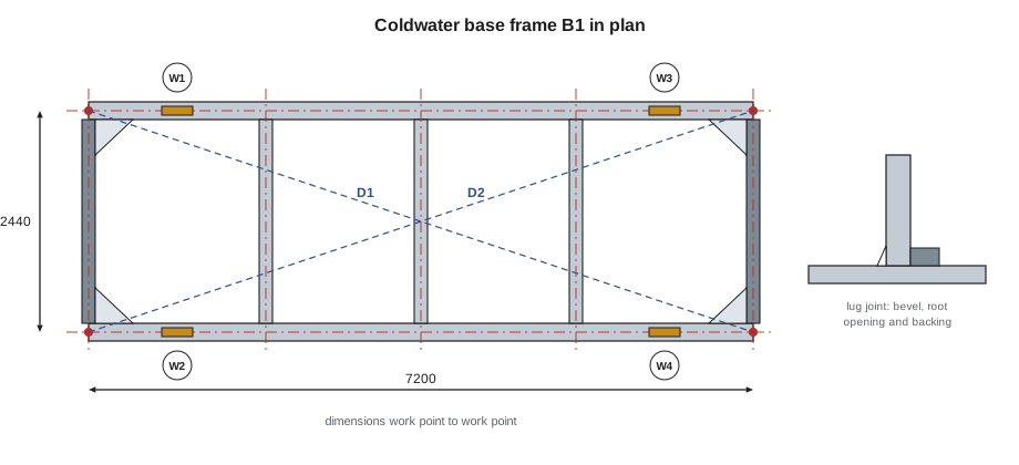
A frame like this is fitted on a flat, level fixture table so that it comes out square and flat. Marta helps Devon plan the sequence so that shrinkage is balanced and every weld can be reached:
- Lay the two long beams on the table at the right spacing, measured from their centre lines to the work points, not from their flange edges.
- Fit the end plates and cross members, tack, and check overall length, width and diagonals before any structural welding.
- Fit the lifting lugs with their backing, and stop for the lug fit-up hold point.
- Fit the gussets.
- Weld in a balanced order: end connections first, opposite corners alternately, then cross members from the centre outward, then gussets, then lugs, with the frame clamped to the table.
- Check dimensions again after welding and before releasing the clamps.
Step 4: fit and check
Devon lays the frame out, tacks it and measures. The tolerances are the ones from the notes and the prequalified joint detail. For the lug joints, the detail gives a root opening with a tolerance as fit up, a root face, and a bevel angle tolerance. For the fillet joints, the codes allow a small gap between the parts before the fillet must be increased: if the gap is larger than a small amount, typically 2 mm (1/16 in), the fillet leg is increased by the amount of the gap, and above a maximum gap the joint must be corrected. For the frame, the overall dimensions and the two diagonals are checked; equal diagonals mean the frame is square.
# Fit-up check of the Coldwater base frame against the drawing and the joint detail tolerances
import math
U = "mm"
# Lifting lug CJP joints: root opening, root face, bevel angle, backing gap
detail = {"gap": (6, (-2, 2)), "face_max": 2, "angle": (45, -5, 10), "backing_gap_max": 2}
lugs = {"W1": (6, 1, 44, 0.5), "W2": (3, 1, 46, 1), "W3": (7, 2, 45, 1), "W4": (6, 1, 47, 3)}
for w, (gap, face, ang, bgap) in lugs.items():
    lo, hi = detail["gap"][0] + detail["gap"][1][0], detail["gap"][0] + detail["gap"][1][1]
    bad = []
    if not lo <= gap <= hi: bad.append(f"root opening {gap} outside {lo:g} to {hi:g}")
    if face > detail["face_max"]: bad.append(f"root face {face} over {detail['face_max']}")
    a0, am, ap = detail["angle"]
    if not a0 + am <= ang <= a0 + ap: bad.append(f"bevel {ang} deg outside {a0 + am} to {a0 + ap}")
    if bgap > detail["backing_gap_max"]: bad.append(f"backing gap {bgap} over {detail['backing_gap_max']}")
    print(f"{w} lug:", "OK" if not bad else "FIX: " + "; ".join(bad))
# Gusset fillet joints: gap between parts and the fillet size to weld
size, allow, max_gap = 6, 2, 5
for w, gap in [("W11", 0), ("W12", 1), ("W13", 3), ("W14", 6)]:
    if gap > max_gap:
        print(f"{w} gusset: gap {gap} {U} over {max_gap} -> refit")
    elif gap > allow:
        print(f"{w} gusset: gap {gap} {U} -> weld fillet {size} + {gap} = {size + gap:g} {U}")
    else:
        print(f"{w} gusset: gap {gap} {U} OK, weld {size} {U}")
# Frame: overall size and squareness from the diagonals
L, W = 7198, 2442          # measured work point to work point
d1, d2 = 7602, 7606
target_L, target_W, tol, diag_tol = 7200, 2440, 3, 5
print(f"length {L} (target {target_L} +/-{tol}):", "OK" if abs(L - target_L) <= tol else "OUT")
print(f"width {W} (target {target_W} +/-{tol}):", "OK" if abs(W - target_W) <= tol else "OUT")
print(f"diagonals {d1} and {d2}, difference {abs(d1 - d2):g} (max {diag_tol}):", "square" if abs(d1 - d2) <= diag_tol else "rack the frame")
print(f"theoretical diagonal {math.hypot(target_L, target_W):.0f} {U}")W1 lug: OK W2 lug: FIX: root opening 3 outside 4 to 8 W3 lug: OK W4 lug: FIX: backing gap 3 over 2 W11 gusset: gap 0 mm OK, weld 6 mm W12 gusset: gap 1 mm OK, weld 6 mm W13 gusset: gap 3 mm -> weld fillet 6 + 3 = 9 mm W14 gusset: gap 6 mm over 5 -> refit length 7198 (target 7200 +/-3): OK width 2442 (target 2440 +/-3): OK diagonals 7602 and 7606, difference 4 (max 5): square theoretical diagonal 7602 mm
The check finds three things to fix before the hold point. Lug W2 has a root opening well under the detail: the lug was tacked tight against a burr on the flange. Lug W4's backing bar stands off the lug by more than the allowed gap, which would leave the root unsupported and invite lack of fusion. Gusset W14 has a gap larger than the code allows for simply increasing the fillet. Gusset W13's gap is inside the maximum but over the small allowance, so its fillet must be welded larger by the amount of the gap, and Devon writes the increased size on the weld map beside W13 so the welder knows. The frame itself is inside its tolerances, and square.
Step 5: correct and record
Devon breaks the tacks on W2, grinds off the burr, and refits the lug with the root opening set by a gauge. He removes the backing on W4, straightens it, and refits it tight with tacks inside the groove, where the root pass will consume them, as the procedure allows. He cuts the gusset at W14 free, trims its edge so it sits down to the flange, and refits it. Then he measures again and records every value on the fit-up check sheet. The sheet lists each joint by weld number, the dimension required, the dimension measured, and his initials. Marta checks a few of his readings at random with her own gauges and signs the sheet as checked.
The record matters as much as the fit. When Lucia arrives for the hold point, she does not take Devon's word for anything, but the sheet tells her where to look first and lets her check a sample of joints against his readings. If her readings agree with his, she can trust the rest; if they do not, she checks everything.
Step 6: the hold point
Lucia inspects the four lug joints. She measures the bevel angle with a protractor gauge, the root face with a rule, and the root opening with a taper gauge at several points along each joint. She checks that the backing is continuous, tight and the right material, by its heat number against the mill certificate on file, and that the joint is clean and dry. She checks the procedure posted at the station and Devon's qualification on the matrix. Then she signs each hold tag and the inspection and test plan, writes the release time, and Devon can weld.
She also looks at one thing that is not on her list: the arrow side of the lug bevels. All four lugs are bevelled on the face toward the frame centre, which is the face the broken arrow points to on the symbol in section E-E. On the plan view, though, the lugs at the far end of the frame are shown mirrored, and a fitter reading the plan alone could have bevelled them on the outboard face. Devon had caught that in step 2 by reading the section, not the plan, and the drawing note says opposite hand for those two lugs. Lucia tells him that is the most common lug mistake she sees.
Step 7: weld, inspect and hand over
Devon welds the frame in the planned sequence with the frame clamped down. He records each weld in the log: weld number, procedure, his identification, the wire lot, the preheat reading and the interpass checks on the lug welds. When the welding is done, he checks every weld for size and appearance with his gauges, marks his identification by each weld, and measures the frame again before releasing the clamps. The frame has shortened by 2 mm (1/16 in) overall from weld shrinkage, as expected, and is still inside its tolerance. He tells Lucia it is ready for final visual inspection, the last hold point before blast and paint.
Lucia's final visual finds one undersized fillet return on a gusset, which Devon builds up while she watches. She marks the lug CJP welds for ultrasonic testing the next morning, after the delay the specification requires for hydrogen cracking to show up, and picks two gusset fillets for magnetic particle testing. Both pass. The frame goes to the blast bay with masking tape over the saddle faying surfaces, and the saddle clips go in the shipping box with a tag that says field weld.
What the job used
Looking back, Devon can trace every step to something in the course:
- Drawing control, piece marks and the bill of materials, to start with the right paper and the right pieces.
- Views, sections, details and work points, to place the pieces and to catch the mirrored lugs.
- General notes, dimensions and tolerances, to know the defaults and how close was close enough.
- Joint types and groove geometry, to prepare and measure the lug bevels.
- The reference line rules, to put every weld on the correct side.
- Fillet, groove, supplementary and examination symbols, to know exactly what weld, contour and test each joint needed.
- Procedures and qualifications, to weld each joint the way it was proven and to know he was allowed to.
Glen's comment when the frame comes back from paint is short: it fits. The vessel sits on the saddles without shims, the pump pads machine clean, and the crane picks the skid from all four lugs at the first try.
Common mistakes
MistakeFitting from the plan view alone on handed pieces.
InsteadRead the section and the opposite-hand note; plan views can be mirrored.
MistakeCorrecting a gap with a bigger fillet when the gap is over the maximum.
InsteadOver the maximum, refit the joint; within it, increase the fillet by the gap and record it.
MistakeChecking the frame dimensions only after welding.
InsteadCheck length, width and diagonals after tacking, before welding, and again after.
MistakeCalling the inspector before checking your own fit-up.
InsteadMeasure and record every joint first; the inspector confirms your check.
MistakeLeaving a fit-up correction off the record.
InsteadRecord the as-fitted values and any changes to weld size on the weld map.
Summary and key terms
- Start every job by checking the package, reading the notes and sorting the pieces by mark.
- Read every weld symbol out loud before fit-up and resolve questions with the detailer.
- Plan fit-up and welding to keep the frame square and every weld reachable.
- Check fit-up against the drawing and joint tolerances, correct what is out, and record the values.
- Hold points stop the work until the inspector has checked and released the joint.
- Record every weld, check it yourself, and hand over with the inspection and the paperwork complete.
- Fit-up
- The positioning and tacking of parts ready for welding, with joint dimensions set.
- Fit-up check sheet
- A record of required and measured joint dimensions for each weld before welding.
- Diagonal check
- Comparing the two diagonals of a rectangular frame to confirm it is square.
- Opposite hand
- A mirror-image version of a part or assembly.
- Root gap allowance
- The gap in a fillet joint above which the fillet size must be increased.
- Release
- The inspector's sign-off that allows work to continue past a hold point.
Practice problems
Work each problem on paper first, then reveal the answer to check.
A frame should be 7200 by 2440 mm. What diagonal should it have?
Show answer
√(7200² + 2440²) = about 7602 mm.
A 6 mm fillet joint has a 3 mm gap, and the allowance is 2 mm with a 5 mm maximum. What fillet size is welded?
Show answer
6 + 3 = 9 mm, and the change is recorded.
The diagonals measure 7602 and 7609 mm with a 5 mm limit. What is needed?
Show answer
The frame is out of square by 7 mm; rack it until the diagonals agree within 5 mm.
Lesson quiz · 5 questions
Score 60% or more to complete this lesson.
Create a free account to save your progress, take quizzes and earn a certificate.