
WLD-220 · Lesson 1 of 12 · 19 min
Drawings in a fabrication shop
Every weld Devon Okafor has made at Hartwell Fabrication so far started with someone telling him what to weld: Marta Kowalchuk pointing at a joint, Glen Teskey handing him a test plate, Lucia Ferreira marking a coupon. That stops this term. Glen moves him onto the Coldwater separator skid as a fitter-welder, and from now on the instructions come on paper. A skid base frame, a pipe spool, a set of bridge stiffeners or a repair to a farm implement arrives in the shop as a set of drawings, and the drawings say what is to be built, from what material, to what size, with which welds, made by which procedure and checked by which test. A welder who can read them works without waiting to be told. A welder who cannot read them waits, guesses, or welds the wrong thing. This course is about reading the drawings that welders use, with most of the time spent on the welding symbol, the compact code that tells a welder exactly what weld goes where. This first lesson explains what drawings a fabrication shop works from, how they are organized, and how to make sure the one in your hand is the one you should be building from.
The general skills of drawing reading, such as orthographic views, scales, lines, title blocks and the way a construction drawing set is put together, were covered in the core blueprint reading course. This course assumes them and builds on them for welded work.
Where a fabrication drawing comes from
A welded product passes through several hands before it reaches the welding bay, and each hand produces its own kind of drawing.
- The engineer of record designs the structure or vessel and produces the design drawings. These show the overall arrangement, the member sizes, the design loads, the connection forces and the welds that are structurally important, often in general terms such as a required weld strength or a typical detail. They are usually stamped by a professional engineer.
- The fabricator's detailer turns the design into shop drawings, also called detail drawings. These show every piece with its exact dimensions, every hole, every cope, every bevel and every weld, so that the shop can build it without making engineering decisions. At Hartwell the detailer is Raj Bhullar, who works in a small office above the tool crib with two screens and a plotter.
- The engineer of record, or the client's engineer, reviews the shop drawings and returns them stamped, for example reviewed, reviewed with comments, or revise and resubmit. Only drawings released for fabrication go to the shop floor.
- The shop uses the released shop drawings to make cut lists, nesting programs for the plasma table, fit-up and welding instructions, and inspection records.
- For work built in the field, erection drawings show where each shipped piece goes, by its piece mark, and the field welds and bolts that join them.
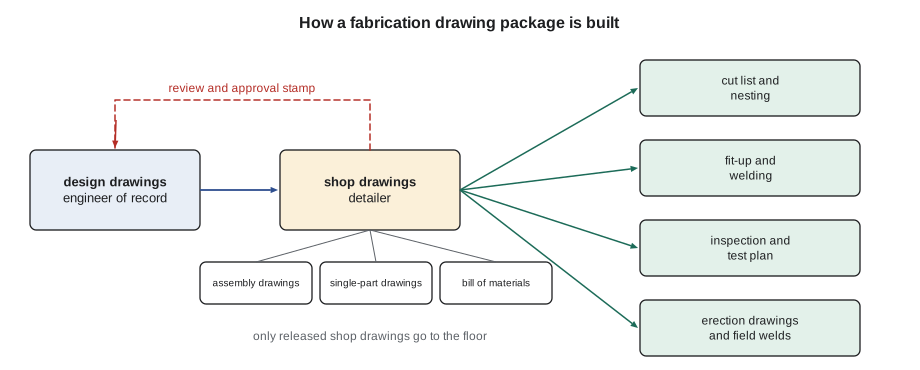
The difference matters to a welder. A design drawing may say that a beam-to-column connection must carry a certain force, or show a typical detail that applies to forty connections. The shop drawing turns that into a specific fillet size, length and location on each piece. If a welder finds that a shop drawing does not seem to match the design intent, the question goes back up the chain through the foreman to the detailer and engineer. It is never settled at the bench by changing the weld.
The kinds of shop drawings
A shop drawing package for a welded product usually contains several kinds of sheets. The names vary between companies, but the functions are the same everywhere.
| Drawing | What it shows | Who uses it most |
|---|---|---|
| General arrangement | The whole product, main dimensions, piece marks of the major assemblies, and notes that apply to everything | Foreman, inspector, fitter |
| Assembly drawing | How pieces fit together into one shipping assembly, with locating dimensions and all the welds that join them | Fitter and welder |
| Single-part or piece drawing | One piece with every cut, hole, bevel and bend dimensioned, ready for the cutting table | Burner, layout, CNC operator |
| Bill of materials | Every piece by mark, quantity, description, material grade and size, often with its weight | Purchasing, burner, inspector |
| Weld map | Every weld identified by a number, with its procedure, welder and inspection record | Welder, inspector, quality control |
| Erection drawing | Where shipped assemblies go on site, with field welds and bolts | Field crew |
On the Coldwater skid, the package for the base frame runs to eleven sheets: a general arrangement of the whole skid, an assembly drawing of the base frame with its weld symbols, six single-part drawings for the beams, gussets and lifting lugs, a drain pan detail, a bill of materials, and a weld map. Devon is given sheets SK-201 to SK-211 in a plastic sleeve and told to read them before he cuts anything.
Piece marks and assembly marks
Every piece and assembly on a shop drawing has a mark, a short code that follows it from the cutting table to the paint shop to the site. Hartwell's marks combine the job, the drawing and the piece. On the Coldwater skid, the base frame is assembly B1, its two long beams are pieces b1 and b2, the cross members are b3 to b6, and the lifting lugs are p11 to p14. Lower-case letters mark loose pieces that are welded into an assembly; capital letters mark the assembly itself. The mark is painted or stamped on each piece as soon as it is cut, so that a beam lying on the floor can be matched to its drawing without measuring it.
Marks also tell the welder which pieces are identical. If four gussets are all mark p7, they are cut from one single-part drawing and are interchangeable. If two look the same but are marked p7 and p8, there is a difference, often a hole, a bevel on the other side, or a mirror image, and swapping them will put a bevel on the wrong face or a hole in the wrong place. Handed pieces, left and right, are a classic trap: the drawing will often show only one and note the other as opposite hand.
The title block and revision block
The title block in the lower right corner of each sheet identifies the drawing: the company, the job, the drawing number, the title, the scale, the units, who drew it and who checked it, and the date. Next to it, or above it, is the revision block: a list of every change made to the drawing since it was first issued, with a revision letter or number, a date, a short description and the initials of the person who approved the change. The current revision is the last line in the block, and it is repeated in the title block.
Changes on the drawing itself are usually marked with a revision cloud, a scalloped line drawn around the changed area, and a small triangle with the revision number beside it. Clouds from older revisions may be removed when a new revision is issued, so only the newest changes are highlighted.
Raj explains the rule he wants every fitter to follow: build only from the current revision, and check it before you start, not after. Revision C of the base frame assembly moved the lifting lugs 150 mm (6 in) outboard after the crane company reviewed the lift plan. A fitter working from revision B would have welded four lugs in the wrong place, each with a full-penetration groove weld that then had to be gouged out, re-fitted and re-tested.
Controlled copies
To stop old revisions getting into the shop, fabricators control their drawings. At Hartwell, every drawing issued to the floor is a controlled copy with a red stamp that says controlled copy, the date, and the name of the person who received it. When a new revision is issued, the document controller collects the old copy and replaces it. Uncontrolled prints, such as a sheet printed for a quick look, are stamped for information only and must not be built from. On a tablet, the shop's drawing viewer shows only the current released revision.
- Before starting work, compare the revision on your drawing with the revision on the drawing register or the viewer.
- If a sheet is marked superseded, void or for information only, do not build from it.
- If you are told verbally that something has changed, ask for the revised drawing or a written change before acting on it.
- If you find a mistake or a conflict, mark it up and send it to the foreman or detailer as a question, often called a request for information. Do not fix it yourself.
Devon checks his sleeve against the register on the office wall and finds that SK-207, the lifting lug detail, is at revision B in his sleeve but revision C on the register, and that SK-210, the drain pan detail, is missing altogether. He takes the sleeve back to the document controller, who swaps the old sheet for a fresh copy and adds the missing one. It takes five minutes.
# Check a sleeve of shop drawings against the drawing register
register = {   # drawing: current released revision
    "SK-201": "C", "SK-202": "C", "SK-203": "A", "SK-204": "A", "SK-205": "B",
    "SK-206": "A", "SK-207": "C", "SK-208": "A", "SK-209": "B", "SK-210": "A", "SK-211": "B",
}
sleeve = {     # what is actually in the fitter's sleeve
    "SK-201": "C", "SK-202": "C", "SK-203": "A", "SK-204": "A", "SK-205": "B",
    "SK-206": "A", "SK-207": "B", "SK-208": "A", "SK-209": "B", "SK-211": "B",
}
ok = True
for dwg, rev in register.items():
    have = sleeve.get(dwg)
    if have is None:
        print(f"{dwg}: missing from the sleeve (current rev {rev})"); ok = False
    elif have != rev:
        print(f"{dwg}: sleeve has rev {have}, register shows rev {rev} -> replace before work"); ok = False
for dwg in sleeve:
    if dwg not in register:
        print(f"{dwg}: not on the register -> ask the document controller"); ok = False
print("sleeve is current" if ok else "do not start until the sleeve is current")SK-207: sleeve has rev B, register shows rev C -> replace before work SK-210: missing from the sleeve (current rev A) do not start until the sleeve is current
The bill of materials
The bill of materials lists every piece in an assembly. Each line gives the mark, the quantity, a description such as plate, wide-flange beam, angle or pipe, the size, the length, the material grade, and often the weight. The bill tells the burner what to cut, tells purchasing what to buy, tells the inspector which mill certificates to check, and tells the crane crew roughly how heavy the finished piece will be.
Canadian bills give steel sizes in metric designations: a W310x60 is a wide-flange beam about 310 mm deep weighing about 60 kg per metre, and plate is listed by thickness, width and length in millimetres, for example PL 12 x 200 x 450. Grades are given by their CSA G40.21 designations, such as 350W for most structural plate and shapes or 350AT for weathering steel with notch toughness.
The weight column is worth checking, because a weight that looks wrong often means a size or length has been mistyped. Plate weight is volume times the density of steel, about 7,850 kg/m³ (0.2836 lb/in³). Rolled shapes are listed by their weight per unit length, so the weight is that figure times the length.
# Material take-off: weight of the Coldwater base frame pieces from the bill of materials
STEEL = 7850            # density of steel, kg/m3
plates = [  # mark, qty, thickness, width, length (mm)
    ("p7 gusset", 8, (12, 200, 300)),
    ("p11 lifting lug", 4, (25, 250, 300)),
    ("p15 drain pan", 1, (6, 1200, 2400)),
]
shapes = [  # mark, qty, section, weight per length (kg/m), length (m)
    ("b1-b2 long beam", 2, "W310x60", 60, 7.2),
    ("b3-b6 cross member", 4, "W250x33", 33, 2.44),
]
total = 0.0
for mark, qty, (t, w, l) in plates:
    each = t * w * l * STEEL / 1e9
    total += qty * each
    print(f"{mark:20} {qty:2} x {each:7.1f} = {qty * each:8.1f} kg")
for mark, qty, sec, wpl, length in shapes:
    each = wpl * length
    total += qty * each
    print(f"{mark:20} {qty:2} x {each:7.1f} = {qty * each:8.1f} kg  ({sec})")
print(f"total steel in assembly B1: {total:,.0f} kg")p7 gusset 8 x 5.7 = 45.2 kg p11 lifting lug 4 x 14.7 = 58.9 kg p15 drain pan 1 x 135.6 = 135.6 kg b1-b2 long beam 2 x 432.0 = 864.0 kg (W310x60) b3-b6 cross member 4 x 80.5 = 322.1 kg (W250x33) total steel in assembly B1: 1,426 kg
The base frame comes out at a little over 1,400 kg (3,100 lb) before welds and paint. Weld metal adds a few percent. When the crane company's lift plan asked for the frame weight, Raj sent this figure with an allowance for welds, and that is why the lugs moved in revision C.
Drawings, specifications and codes
A drawing does not stand alone. Notes on the drawing refer to the project specification, which sets the requirements for material, welding, inspection, painting and documentation, and the specification refers to codes and standards. A note such as all welding to CSA W59 or all welding to AWS D1.1 brings in hundreds of pages of rules about joint details, workmanship, procedures, welder qualification and acceptance criteria. Where the drawing and the specification conflict, the contract usually says which governs; in practice the shop asks.
For the Coldwater skid, the structural base is welded to CSA W59 by a company certified by the Canadian Welding Bureau to CSA W47.1, and the vessel and piping are welded to the ASME code under ABSA registration. Each drawing says which applies to which welds.
A welder needs to know which code applies to a weld, because it decides the procedure that must be used, the qualification the welder must hold, and the acceptance criteria the inspector will apply. Two fillet welds that look identical on paper may be governed by different documents.
Reading a drawing before you start
Marta has a routine for any new drawing, and she makes Devon say it back to her:
- Read the title block: job, drawing number, title, revision, scale and units.
- Read the revision block and look for clouds, so you know what changed.
- Read the general notes: code, material, default weld sizes, tolerances, finishes, inspection.
- Look at the general arrangement or main view to understand what the thing is and how it sits.
- Find every piece on the bill of materials and check that you have it, by mark.
- Find every weld symbol and make sure you understand it. Ask about any you do not.
- Check the welding procedure referenced for each weld, and that you are qualified for it.
- Look for hold points: places where the inspector must see the fit-up or a pass before you continue.
It takes Devon most of a morning to go through the base frame package this way the first time. Marta tells him it will take twenty minutes by the end of the course, and that the morning is the cheapest part of the job.
Common mistakes
MistakeBuilding from the design drawing because the shop drawing is not ready yet.
InsteadWait for the released shop drawing; design drawings leave decisions to the detailer.
MistakeWorking from a sheet without checking its revision.
InsteadCompare the revision with the register or viewer before starting.
MistakeSwapping two pieces that look the same but have different marks.
InsteadDifferent marks mean different pieces; check for handed or mirror-image details.
MistakeCorrecting an apparent error on the drawing at the bench.
InsteadSend a question to the foreman or detailer and wait for a written answer.
MistakeIgnoring the general notes because the views look complete.
InsteadNotes carry default weld sizes, codes, tolerances and inspection requirements.
Summary and key terms
- Fabricators build from released shop drawings prepared by a detailer from the engineer's design drawings.
- A package includes a general arrangement, assembly drawings, single-part drawings, a bill of materials and often a weld map.
- Piece marks follow each piece from cutting to shipping; different marks mean different pieces.
- The title block and revision block identify the drawing and its current revision; clouds show recent changes.
- Only controlled copies of the current revision are built from.
- Drawing notes bring in the project specification and the welding code, which govern procedures, qualification and acceptance.
- Design drawing
- A drawing by the engineer of record showing the design, member sizes and required connection strength.
- Shop drawing
- A fabricator's drawing that dimensions every piece and weld so that the shop can build without making design decisions.
- Piece mark
- A code that identifies each piece and assembly on the drawings and on the steel.
- Revision block
- The list of changes to a drawing, with revision letters, dates and approvals.
- Controlled copy
- A drawing issued to the floor under document control and replaced when revised.
- Bill of materials
- A list of every piece with its mark, quantity, size, grade and weight.
Practice problems
Work each problem on paper first, then reveal the answer to check.
A plate is 20 mm thick, 300 mm wide and 400 mm long. What does it weigh?
Show answer
20 x 300 x 400 = 2,400,000 mm³ = 0.0024 m³; x 7,850 = about 18.8 kg.
A W200x46 is 6.0 m long. What does it weigh?
Show answer
46 kg/m x 6.0 m = 276 kg.
Your sleeve has rev B of a sheet and the register shows rev C. What do you do?
Show answer
Stop and exchange the sheet for the current controlled copy before working from it.
Lesson quiz · 5 questions
Score 60% or more to complete this lesson.
Create a free account to save your progress, take quizzes and earn a certificate.