
SMW-330 · Lesson 8 of 12 · 19 min
Balancing variable-air-volume systems and terminal units
The Ashgrove library runs at constant volume: RTU-2 delivers the same airflow whenever it runs, and the manual dampers share it. Most of the Eastgate addition, like most modern commercial buildings, runs differently. Its air handlers supply a variable-air-volume system, in which each zone has a terminal unit, a VAV box, that changes the airflow to the zone as the cooling load changes, and the supply fan slows down or speeds up to keep a set duct pressure. Balancing a VAV system is as much about checking and setting controls as it is about moving dampers, and it is done with the controls contractor working alongside the TAB technician.
How a VAV system works
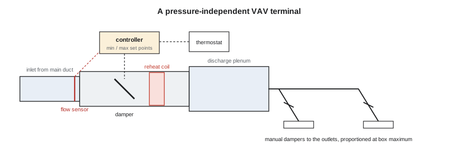
A VAV box is a short section of duct with a motorized damper, an airflow sensor and a controller. The zone thermostat asks for more or less cooling, and the controller moves the damper to deliver an airflow between a minimum and a maximum set in its program. Boxes in perimeter zones and in cold climates often have a reheat coil, electric or hot water, that warms the minimum airflow when the zone needs heat. Some boxes have a small fan, either in series, running all the time, or in parallel, running only for heating, to mix in ceiling plenum air. At the air handler, a duct static pressure sensor, usually two thirds of the way down the main duct, tells the supply fan's variable-frequency drive to keep that pressure at its set point, so that every box always has enough pressure available to reach its airflow.
Because the boxes control their own airflow, the downstream ductwork from each box to its outlets is balanced much like a small constant-volume system, but the box itself is not balanced with a manual damper. Instead the TAB technician verifies that the box's airflow sensor reads correctly, that the controller's minimum and maximum airflows are set to the design values, and that the box can actually reach its maximum at the system's design static pressure.
Pressure-independent boxes and the flow sensor
Most VAV boxes are pressure independent: the controller measures the airflow through the box with a multipoint pitot-type sensor at the inlet, usually a cross or ring with many holes, and adjusts the damper to hold the airflow it wants regardless of changes in upstream pressure. The sensor produces a differential pressure that is related to the airflow through a flow coefficient, often called a K factor, published by the box manufacturer for each inlet size.
The controller uses that relationship to calculate airflow. If the K factor programmed into the controller is wrong for the box size, or the sensor tubes are reversed, cracked or pinched, or the inlet duct is too short and gives the sensor a distorted profile, the controller's displayed airflow will not match the real airflow, and every setting based on it will be wrong. The TAB technician's job is to measure the real airflow independently, by hood readings at the outlets or a traverse of the inlet duct, and compare it with the controller's reading. If they disagree, the controller's flow coefficient or calibration factor is adjusted, by the controls contractor or by the technician with the controls contractor's tools, until they agree.
import math
# Check a VAV box flow sensor: controller reading vs measured airflow, then correct the K factor
k_prog = 63.0          # flow coefficient programmed in the controller
dp = 32.0              # sensor differential pressure at maximum, Pa
q_ctrl = k_prog * math.sqrt(dp)
q_meas = 322          # hood total of the box's outlets, L/s
print(f"controller shows {q_ctrl:.0f} L/s, measured {q_meas} L/s ({100*q_meas/q_ctrl:.0f}%)")
k_new = q_meas / math.sqrt(dp)
print(f"corrected K = {k_new:.1f}")
q_min_design = 110
dp_min = (q_min_design / k_new) ** 2
print(f"at the design minimum of {q_min_design} L/s the sensor will read only {dp_min:.1f} Pa")controller shows 356 L/s, measured 322 L/s (90%) corrected K = 56.9 at the design minimum of 110 L/s the sensor will read only 3.7 Pa
The example shows a common finding: the controller thinks the box is delivering about 356 L/s at maximum, but the outlets actually receive less. Correcting the K factor brings the controller into agreement. The last line shows a second issue. At the design minimum airflow, the sensor's differential pressure is small, a few pascals, and the controller's transducer may not read it accurately. That is why manufacturers publish a minimum controllable airflow for each box size, and why the engineer sets minimum airflows above it. A TAB technician who finds a scheduled minimum below the box's controllable minimum reports it.
Setting minimum and maximum airflow
The design drawings or schedules give each VAV box a maximum cooling airflow, a minimum airflow, and sometimes a separate heating airflow for boxes with reheat. The minimum is often set by ventilation requirements: the zone must get enough outdoor air even when it needs no cooling. At Eastgate, minimums are also set by the air change rates required in health care spaces and, for rooms with pressure relationships, by the need to keep the right offset between supply and exhaust at all times, which lesson 10 explains.
The usual procedure is to have the controls contractor command each box to its maximum, verify and correct the airflow, then command it to its minimum and verify again, and finally to the heating airflow if there is one. At each step the downstream outlets are read and, if the box serves several outlets, their manual dampers are proportioned using the method of lesson 7 with the box at maximum. The TAB report records, for each box, the design and measured maximum and minimum, the controller reading, the K factor before and after, and the damper position or percentage open at maximum.
Fan and static pressure set point
With every box able to reach its airflow, the TAB technician and controls contractor set the supply fan's static pressure set point. The aim is the lowest set point that still lets every box reach its maximum when it needs to. A set point that is too high wastes fan energy, makes boxes throttle hard and noisily, and can over-pressurize ducts; one that is too low starves the boxes furthest from the fan. The usual check is to command all boxes to maximum, or a realistic diversity of them, and see whether the box with the least pressure available, the critical box, can still reach its maximum with its damper not fully open.
Many modern systems use static pressure reset, in which the controls lower the set point when no box is near fully open and raise it when one is. This saves energy over the year and is required by some energy codes for larger systems. The TAB technician's role is to establish the design set point and the minimum and maximum limits of the reset, and to verify that the fan responds smoothly. The controls sequences themselves are commissioned by the commissioning authority.
# Supply fan check on an Eastgate VAV air handler: fan law estimate of energy saved by a lower static pressure set point
q_design = 9400         # design supply airflow at full load, L/s
sp_old, sp_new = 375, 250   # duct static set points, Pa
fixed = 700           # pressure the fan needs at design flow apart from the controlled duct pressure, Pa
# fan power at the same flow is roughly proportional to total pressure
p_old = fixed + sp_old
p_new = fixed + sp_new
print(f"fan pressure at design flow: {p_old} -> {p_new} Pa ({100*(1-p_new/p_old):.0f}% less)")
print("power saving at full load about the same percentage; larger at part load as boxes close")fan pressure at design flow: 1075 -> 950 Pa (12% less) power saving at full load about the same percentage; larger at part load as boxes close
Return, relief and outdoor air in VAV systems
When the supply airflow varies, the return and outdoor airflows have to follow, or the building pressure changes. In a system with a return fan, the return fan is controlled to track the supply, often with a fixed difference between them so that the building stays slightly positive. In a system with a relief fan or relief dampers, the relief is controlled from a building pressure sensor. In either case, the minimum outdoor airflow must be maintained as the supply drops, which simple fixed damper positions do not do, because the mixing box pressures change with the fan speed. Many systems use an airflow measuring station in the outdoor air duct for this. The TAB technician measures the outdoor air at design and minimum supply, verifies the measuring station against a traverse, and records the results.
Kai's first VAV lesson at Eastgate came when the air handler's outdoor air station read 1,900 L/s (4,000 cfm) and his traverse of the outdoor air duct read 30 percent less. The station's sensor had been installed too close to the intake louvre, in turbulent flow, and the controls contractor had to apply a field correction until the installer moved it.
Fan-powered boxes and dual-duct systems
Series fan-powered boxes have a small fan that runs whenever the zone is occupied, mixing primary air from the VAV system with plenum air. The box fan's airflow is set, usually with a speed controller on the fan motor or an electronically commutated motor, to slightly more than the maximum primary airflow, so the box never pushes primary air backward out of its plenum inlet. Parallel fan-powered boxes run their fan only in heating. Dual-duct systems, less common in new work, have a cold and a hot duct to each box and mix them. In each case the TAB technician reads and sets each air stream separately and records the results.
Working with the controls contractor
VAV balancing cannot be done without the controls contractor, or at least without access to the controls through a laptop or the building automation workstation. Before balancing starts, Marisol confirms that every box is online, that the controller's box size, K factor and set points have been entered, that the static pressure sensor and its set point are in place, and that someone from the controls contractor will be on site with the TAB group for the first days. The two groups agree on a sequence: which floor first, how boxes will be commanded, and how changes to K factors will be recorded so that both companies have the same final numbers.
Both parties also agree on what will happen to the settings after balancing. A K factor changed in the controller and not recorded is lost the next time the controller is replaced or reprogrammed. The TAB report lists the final values, and the controls contractor's as-built program should match it.
Worked problem
A VAV box that cannot reach maximum
An Eastgate box designed for 420 L/s at maximum reaches only 340 L/s with its damper 100 percent open, at the design duct static pressure of 250 Pa. Its downstream outlets are proportioned. What should Kai check?
Show solution
- Confirm the measured airflow by hood total or inlet traverse, not just the controller display.
- Read the static pressure at the box inlet; if it is much less than the duct set point, look upstream for a restriction or an undersized runout.
- Check the downstream duct and flexible connections for restriction, and the reheat coil for blockage.
- If the inlet pressure is adequate and the box is still short, report it to the engineer; raising the system set point to satisfy one box wastes energy for every other box.
Answer: A box at 100 percent open and short of airflow has a resistance problem, not a controls problem, and the fix belongs to the installer or the designer.
Common mistakes
MistakeTrusting the VAV controller's airflow display.
InsteadMeasure the real airflow and correct the flow coefficient.
MistakeSetting a minimum airflow below the box's controllable minimum.
InsteadReport it; the engineer should raise it or change the box.
MistakeRaising the static pressure set point to help one starved box.
InsteadFind the restriction on that box's path.
MistakeLeaving return and outdoor air unchecked at minimum supply.
InsteadMeasure outdoor air at design and minimum supply.
MistakeChanging K factors without recording them.
InsteadList final values in the TAB report and the controls as-built.
Summary and key terms
- VAV boxes vary airflow between minimum and maximum set points; the fan holds a duct static pressure set point.
- Pressure-independent boxes calculate airflow from a sensor differential pressure and a flow coefficient.
- TAB verifies real airflow against the controller and corrects the coefficient.
- Downstream outlets are proportioned with manual dampers at box maximum.
- The static pressure set point should be the lowest that lets the critical box reach maximum.
- Return, relief and outdoor air must track the supply; controls work is shared with the controls contractor.
- VAV box
- A terminal unit with a controlled damper that varies airflow to a zone.
- Pressure independent
- Holding airflow to a set point regardless of upstream pressure changes.
- Flow coefficient (K factor)
- The constant relating a flow sensor's differential pressure to airflow.
- Minimum controllable airflow
- The lowest airflow a box can measure and hold accurately.
- Static pressure set point
- The duct pressure the supply fan is controlled to maintain.
- Critical box
- The box with the least pressure available, which sets the minimum duct set point.
Practice problems
Work each problem on paper first, then reveal the answer to check.
A box sensor reads 36 Pa with K = 60. What airflow does the controller show?
Show answer
60 × √36 = 360 L/s.
The outlets read a total of 324 L/s. What is the corrected K?
Show answer
324 ÷ 6 = 54.
Why are minimum airflows not set too low?
Show answer
The sensor signal becomes too small to read and the box cannot control accurately.
What is static pressure reset?
Show answer
Lowering the duct set point when no box needs it, raising it when one does, to save fan energy.
Lesson quiz · 5 questions
Score 60% or more to complete this lesson.
Create a free account to save your progress, take quizzes and earn a certificate.