
SMW-330 · Lesson 12 of 12 · 20 min
Capstone: balancing the Ashgrove library system
This capstone follows the Ashgrove library system from the day Kai and Marisol opened the drawings to the day the commissioning authority signed off the TAB report. It brings together everything in the course: the design review and pre-balance inspection from lesson 1, the pressures and fan behaviour from lessons 2 and 3, the instruments, traverses and outlet readings from lessons 4 to 6, the proportional method from lesson 7, the fan adjustment from lesson 9, the room pressure checks from lesson 10 and the report from lesson 11. It is also the end of a story that started in SMW-220, when Kai fabricated the library trunk in the shop, and continued in SMW-310, when Sean's crew hung it and leak-tested it.
The system
The library is served by RTU-2, a packaged rooftop unit on a roof curb above the library's east end, with a belt-driven forward-curved supply fan, an adjustable motor sheave, a 2.2 kW (3 hp) 600 V motor, filters, a cooling coil and a gas heating section. Its design supply is 1,660 L/s at an external static pressure of 500 Pa, with 300 L/s of outdoor air. The supply drops straight down through the roof into a 1200 × 600 mm plenum, then runs along the library ceiling as trunk T1 (900 × 450 mm), T2 (600 × 450 mm) and T3 (450 × 300 mm), with six 250 mm round branches (B1 to B6) at 200 L/s and four 200 mm branches (B7 to B10) at 115 L/s, each with a volume damper near the trunk and a square ceiling diffuser. Two return grilles near the west end return air through a short duct to the unit. Fire dampers FD-1 and FD-2 sit where the trunk crosses the rated wall between the library and the corridor.
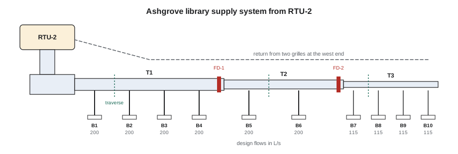
Week 1: design review and pre-balance
Marisol's design review, done in May while the school was still in session, had already produced two results. First, she checked that the outlet design flows added up to the unit, as Kai did in lesson 1, and they did. Second, she asked for test holes and a straight run for the T1 traverse, which the shop drawings showed was short, and for the return elbow at the unit to be checked for its turning vanes; both notes went to Sean's crew before the ceiling closed. In the first week of the TAB work in July, Kai did the pre-balance inspection with a checklist: construction filters had been left in RTU-2 and were replaced with the specified clean filters; all ten branch dampers were found open and their quadrants accessible; FD-2's blades had been knocked partly closed during the drywall repair recorded in SMW-310 and were reset and checked; the ceiling tiles were in; and the controls contractor confirmed the unit could be run in occupied mode with the outdoor air damper at its minimum position.
The day ended with the first readings at the unit: fan speed 1,050 rpm by optical tachometer, motor current within the nameplate, and a static pressure profile through RTU-2 with a filter drop close to the clean-filter value on the submittal.
Week 1: the first traverse and outlet readings
The T1 traverse, a 5 × 5 log-Tchebycheff grid in the straight piece between the drop elbow and the first takeoff, gave 1,520 L/s, 92 percent of design, as lesson 5 showed. The hood readings at the ten outlets, all dampers open, added up to 1,474 L/s, 89 percent, with B1 at 121 percent and B10 at 55 percent, the classic pattern of lesson 6. B4's hood reading agreed with a branch traverse within 4 percent, so the hood readings were accepted without correction.
One reading did not fit the pattern. B8, in the middle of T3, read 62 percent of design with its damper wide open, much lower than its neighbours. Kai lifted the tile and found the flexible connection kinked around a sprinkler branch line, the deficiency written up in lesson 11. Sean's crew rerouted it the next morning, and B8 came up into line with the other outlets on T3.
Week 2: proportioning
With B8 fixed, Kai and Marisol proportioned the outlets using the method of lesson 7. B10, at the end of T3, was the index outlet. Kai worked on the dampers above the ceiling with a radio while Marisol read the hood, starting at B9 next to the index and working back toward the fan. After the first pass the ratios had closed to within about 6 percent of each other; after the second, within 2 percent, at about 86 percent of design. Then they proportioned the trunks at the branch level, as in the T2 example of lesson 7, comparing the traverse planes on T2 and T3 with the outlets they fed.
# Proportioning record for the Ashgrove library: ratios after each pass
design = [200, 200, 200, 200, 200, 200, 115, 115, 115, 115]
first = [242, 223, 208, 174, 157, 144, 100, 85, 78, 63]
pass1 = [176, 168, 167, 171, 165, 162, 102, 96, 98, 91]
pass2 = [172, 171, 170, 173, 171, 170, 100, 98, 99, 98]
for name, row in (("dampers open", first), ("after pass 1", pass1), ("after pass 2", pass2)):
    r = [x / d for x, d in zip(row, design)]
print(f"{name:13s} lowest {100*min(r):.0f}% highest {100*max(r):.0f}% spread {100*(max(r)-min(r)):.0f} points total {sum(row)} L/s")dampers open lowest 55% highest 121% spread 66 points total 1474 L/s after pass 1 lowest 79% highest 89% spread 10 points total 1396 L/s after pass 2 lowest 85% highest 87% spread 2 points total 1422 L/s
The record shows the method working: the spread of ratios between the lowest and highest outlet fell from about 66 points with every damper open to about 3 points after two passes. The total fell a little at the same time, because closing dampers adds resistance, which is why the fan adjustment comes last.
Week 2: the fan
With the system proportioned, RTU-2 delivered about 1,430 L/s. Marisol and Kai first dealt with the return elbow at the unit, whose vanes had been set at the wrong angle, as lesson 9 described; resetting them raised the fan's delivery to 1,480 L/s at the same speed. The motor check showed that the 12 percent increase needed would keep the motor within its 2.7 A nameplate. With RTU-2 locked out, Kai closed the adjustable motor sheave three and a half turns, reset belt tension and checked alignment with a straightedge. On restart the fan ran at 1,178 rpm and the outlets read about 96 percent of design. A further half turn took the fan to 1,205 rpm, and the final T1 traverse read 1,702 L/s with the motor drawing 2.6 A.
Because the specification called for fixed sheaves after balancing, Keelson ordered a fixed motor sheave of the equivalent pitch diameter and a matched belt. When it was fitted the following week, Kai confirmed that the fan speed and current were unchanged and rechecked belt tension two days later.
Week 2: final readings
# Final outlet readings, Ashgrove library, against plus or minus 10 percent
design = [200, 200, 200, 200, 200, 200, 115, 115, 115, 115]
final  = [203, 196, 201, 198, 195, 206, 112, 117, 114, 109]
names = [f"B{k}" for k in range(1, 11)]
worst = 0
for n, d, f in zip(names, design, final):
    pct = 100 * f / d
    worst = max(worst, abs(pct - 100))
    print(f"{n}: design {d}, final {f} L/s, {pct:.0f}%")
print(f"total {sum(final)} of {sum(design)} L/s = {100*sum(final)/sum(design):.1f}%")
print(f"largest deviation {worst:.1f} points:", "all within tolerance" if worst <= 10 else "outside tolerance")B1: design 200, final 203 L/s, 102% B2: design 200, final 196 L/s, 98% B3: design 200, final 201 L/s, 100% B4: design 200, final 198 L/s, 99% B5: design 200, final 195 L/s, 98% B6: design 200, final 206 L/s, 103% B7: design 115, final 112 L/s, 97% B8: design 115, final 117 L/s, 102% B9: design 115, final 114 L/s, 99% B10: design 115, final 109 L/s, 95% total 1651 of 1660 L/s = 99.5% largest deviation 5.2 points: all within tolerance
Every outlet finished within about 5 percent of design, comfortably inside the specified 10 percent, with B10, the index outlet, still at the low end of the range and its damper still wide open. The total at the outlets was within one percent of design, and the trunk traverses agreed with the outlets as shown in lesson 11. Kai marked every damper quadrant with paint and a scribe line and recorded the positions.
The return grilles, read with a vane anemometer and the manufacturer's Ak, totalled 1,370 L/s, and the outdoor air, measured by a traverse in the outdoor air duct at the unit, was 310 L/s against a design of 300 L/s. With the library's doors closed, the room read about +2 Pa to the corridor, slightly positive, which matched the design's intent that the library supply a little air to the corridor exhaust.
Week 3: the report and the spot-check
Kai wrote up the data sheets, and Marisol checked them line by line: outlets against trunks, trunks against the fan, instrument list and calibration dates, the static pressure profile, the fan and motor data, the sheave and belt sizes, the deficiencies and their status. Two deficiencies were listed, both resolved: B8's kinked flexible connection and the return elbow vanes. A third note recorded FD-2's blades found partly closed in the pre-balance inspection and reset. Marisol signed the report as the certified TAB supervisor and sent it to the engineer and the commissioning authority.
The school board's commissioning authority came in the third week of August, with her own calibrated hood. She chose two outlets, B2 and B9, and the RTU-2 traverse at random. Her readings on the two outlets were within 4 percent of the report and her traverse within 3 percent, inside the allowance her plan set for spot-checks, and she accepted the TAB report for the library.
# Commissioning spot-check: reviewer's readings against the TAB report
report = {"B2": 196, "B9": 114, "RTU-2 traverse": 1702}
review = {"B2": 189, "B9": 117, "RTU-2 traverse": 1655}
allow = 0.10
for name, r in report.items():
    d = (review[name] - r) / r
print(f"{name}: report {r} L/s, reviewer {review[name]} L/s, {100*d:+.1f}% ->", "accepted" if abs(d) <= allow else "rejected")B2: report 196 L/s, reviewer 189 L/s, -3.6% -> accepted B9: report 114 L/s, reviewer 117 L/s, +2.6% -> accepted RTU-2 traverse: report 1702 L/s, reviewer 1655 L/s, -2.8% -> accepted
September: occupancy
Marisol's practice is to ask for comfort feedback once a balanced space is in use. In late September the school reported that the reading area near B1 felt drafty. Kai visited after school, used a smoke pencil to look at the air pattern, and found that B1's adjustable pattern controller had been set to throw toward a seating area that was not on the original furniture plan. He reset the pattern to throw away from the seats without changing the damper or the airflow, recorded the change in an addendum to the report, and the complaint stopped.
What the job taught
Looking back, Kai listed the lessons he took from the library job. The design review paid for itself: test holes and access in the right places made the work faster. The pre-balance inspection found three problems before any reading was taken. The readings that did not fit the pattern, B8 and the return elbow, were the most useful, because each pointed to a real fault that a damper could not fix. The proportional method turned a fiddly job into a methodical one. Checking the motor before touching the sheave avoided overloading it, and fixing the return loss first meant the fan needed less speed and the building will use less energy for as long as the unit runs. And a report that shows real readings, deficiencies and all, was accepted on the first spot-check.
Halima's comment, when Marisol showed her the report, was that the library was the first system in Keelson's history that the company had designed shop drawings for, fabricated, installed, sealed, leak-tested and balanced itself, and that the record from the shop's cut list to the commissioning sign-off was now in one file. In SMW-410 the same group will take on the Brine & Ember kitchen exhaust, where the balancing ties into the hood and fire safety rules.
Worked problem
Checking the final fan speed
After resetting the return vanes, RTU-2 delivered 1,480 L/s at 1,050 rpm. The final traverse read 1,702 L/s at 1,205 rpm. Is that consistent with the fan laws?
Show solution
- Speed ratio: 1,205 ÷ 1,050 = 1.148.
- Predicted airflow: 1,480 × 1.148 = 1,699 L/s.
- Measured: 1,702 L/s, within 0.2 percent of the prediction.
- The system did not change between the readings, so the fan laws apply and the readings are consistent.
Answer: The final traverse agrees with the fan-law prediction, which gives Marisol confidence in both readings before she signs the report.
Common mistakes
MistakeStarting to balance before the pre-balance inspection.
InsteadInspect first; the library inspection found construction filters and a partly closed fire damper.
MistakeTreating an outlet far below its neighbours as a damper problem.
InsteadLook for a restriction such as a kinked flexible connection.
MistakeSpeeding up the fan before reducing avoidable losses.
InsteadFix losses such as misset turning vanes first, then adjust speed.
MistakeLeaving an adjustable sheave in place when the specification calls for fixed sheaves.
InsteadFit a fixed sheave of equivalent diameter and confirm speed and current.
MistakeClosing the job without following up after occupancy.
InsteadAsk for comfort feedback and record any adjustments in an addendum.
Summary and key terms
- The library job ran from design review and pre-balance through traverses, outlet readings, proportioning, fan adjustment and final readings.
- Readings that did not fit the pattern revealed real deficiencies.
- Two passes of proportioning closed the spread of outlet ratios to a few points.
- Reducing the return loss first limited the speed increase and kept the motor within its nameplate.
- Every outlet finished within about 5 percent of design; totals agreed across outlets, trunks and fan.
- The report passed the commissioning spot-check; a follow-up after occupancy fixed a draft without changing airflow.
- Pre-balance checklist
- The list of items confirmed before readings start.
- Index path
- The path from fan to index outlet, left with all dampers open.
- Final readings
- The full set of measurements taken after all adjustments.
- Addendum
- A later addition to a report recording changes made after it was issued.
- Pattern controller
- An adjustable part of a diffuser that changes the direction of its air.
- Fixed sheave
- A sheave with a fixed pitch diameter, fitted after balancing.
Practice problems
Work each problem on paper first, then reveal the answer to check.
After proportioning, outlets read 86 percent of design. What fan speed increase would bring them to design if the system does not change?
Show answer
1 ÷ 0.86 = 1.163, about 16 percent.
Why was the needed speed increase only about 15 percent in the end?
Show answer
Resetting the return vanes reduced the system resistance before the speed change.
A spot-check reads 189 L/s where the report shows 196 L/s. Is it within 10 percent?
Show answer
−3.6 percent; yes.
What three deficiencies or notes were in the library report?
Show answer
B8's kinked flexible connection, the misset return elbow vanes and FD-2 found partly closed.
Lesson quiz · 5 questions
Score 60% or more to complete this lesson.
Create a free account to save your progress, take quizzes and earn a certificate.