
SMW-330 · Lesson 5 of 12 · 19 min
Duct traverses
The most reliable way to measure the airflow in a duct is a traverse: a set of velocity readings taken at defined points across the duct's cross-section, averaged and multiplied by the area. It is the reference method for fan totals and main branches, the measurement every other method is checked against, and the one a commissioning authority trusts when the numbers are disputed. It is also the method that most rewards care. A traverse in a good location with the right points takes twenty minutes and gives an answer within a few percent; a traverse in a bad location gives a precise-looking number that can be badly wrong.
Why many points are needed
Air in a duct does not move at one speed. Friction slows the air near the walls, so the velocity is lowest at the edges and highest near the centre. After an elbow, the air piles up toward the outside of the turn; after a branch takeoff, it can swirl; downstream of a fan, the velocity profile is lopsided and pulsing. A single reading samples one small part of this pattern. A traverse samples the whole section at points chosen so that each represents a known share of the area, and the average of the velocities is the true average velocity.
Two point layouts are in common use. In the equal-area method, the duct section is divided into equal areas and a reading is taken at the centre of each. In the log-Tchebycheff method, points are placed at positions calculated to account for the slower air near the walls, so that a simple average of the readings gives an accurate result with fewer points. ASHRAE Standard 111 and the TAB procedural standards describe both and favour log-Tchebycheff, especially for rectangular ducts.
Point layouts for rectangular ducts
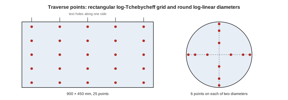
For a rectangular duct, a grid of points is laid out across the width and the height. Each side is divided into a number of traverse lines depending on its length; a common rule is at least five lines on sides up to about 750 mm, and more on larger sides, with a minimum of 25 points in total for most ducts. The log-Tchebycheff positions place the points closer to the walls than an equal spacing would.
| Lines across a side | Positions as a fraction of the side, from one wall |
|---|---|
| 5 | 0.074, 0.288, 0.500, 0.712, 0.926 |
| 6 | 0.061, 0.235, 0.437, 0.563, 0.765, 0.939 |
| 7 | 0.053, 0.203, 0.366, 0.500, 0.634, 0.797, 0.947 |
Test holes are drilled in one side of the duct at each line position across the width, and the pitot tube is pushed in to each depth position across the other dimension. The pitot stem is marked in advance with tape or a marker at each depth, measured from the inside wall, so the technician only has to slide it to the next mark and hold it square to the flow.
Point layouts for round ducts
For a round duct, readings are taken along two or three diameters at right angles, through two or three test holes spaced around the circumference. On each diameter, points are placed at positions that divide the section into rings of equal area or, in the log-linear method, at positions corrected for the wall effect. ASHRAE 111 gives the positions. Six points on each of two diameters is a common minimum for smaller ducts, with more points on larger ones.
| Points on a diameter | Positions as a fraction of the diameter, from one wall |
|---|---|
| 6 | 0.032, 0.135, 0.321, 0.679, 0.865, 0.968 |
| 8 | 0.021, 0.117, 0.184, 0.345, 0.655, 0.816, 0.883, 0.979 |
Choosing a traverse location
The location matters more than any other factor. The flow at the traverse plane should be as uniform and steady as possible, which means in a long straight section, well away from fans, elbows, transitions, dampers and branch takeoffs. The usual guidance is at least several duct diameters of straight duct upstream of the plane and a shorter length downstream, with more needed after fans and sharp fittings. The equivalent diameter of a rectangular duct is used for this purpose.
Real buildings rarely provide the ideal. The Ashgrove library trunk T1 runs only a short distance from the RTU-2 drop before its first branch takeoff. Marisol chose the traverse plane in the longest straight piece of T1, between the drop elbow and the first takeoff, and the distance upstream of the plane was less than the standard asks for. Where the location is not ideal, the TAB procedure is to take more points, check the profile for reversed or very uneven flow, and compare the result with other measurements, such as the sum of the branches, and state the limitation in the report.
A traverse should never be taken in a location where some readings show reversed flow, which happens in the eddy just past an elbow or a sudden expansion, or where the readings are so uneven that a few points dominate the average. If a quick check shows that, the technician moves the plane.
At Eastgate, the main exhaust duct for the isolation suite ran 6 m straight along a corridor ceiling before rising to the roof fan, and Kai traversed it about 2 m from the downstream end, which gave plenty of straight duct upstream.
Taking and calculating the traverse
At each point the technician holds the pitot tube square to the flow, waits for the reading to settle, and records the velocity pressure, or the velocity if the manometer converts it. The key step in the calculation is that the average velocity is the average of the velocities at the points, not the velocity of the average velocity pressure. Because velocity goes with the square root of velocity pressure, averaging pressures first and then taking the square root gives a slightly high answer, especially when the profile is uneven. Digital manometers that average velocities automatically do this correctly.
import math
# Log-Tchebycheff traverse of Ashgrove trunk T1 (5 x 5 points), velocity pressures in Pa
vp = [[5.8, 8.2, 8.7, 7.9, 5.2], [7.3, 10.1, 10.9, 9.9, 6.7], [7.9, 10.8, 11.6, 10.6, 7.2], [7.6, 10.3, 11.2, 10.2, 7.0], [6.2, 8.9, 9.5, 8.7, 5.8]]
c = 1.29                      # standard-air constant
w, h = 900, 450              # inside dimensions, mm
pos5 = [0.074, 0.288, 0.500, 0.712, 0.926]
print("hole positions across the width:", ", ".join(f"{p*w:.0f}" for p in pos5), "mm")
print("pitot depths across the height:  ", ", ".join(f"{p*h:.0f}" for p in pos5), "mm")
v = [c * math.sqrt(p) for row in vp for p in row]
v_avg = sum(v) / len(v)
v_wrong = c * math.sqrt(sum(p for row in vp for p in row) / len(v))   # averaging pressures first
area = w * h / 1e6
print(f"average velocity {v_avg:.2f} m/s (pressure-first method would give {v_wrong:.2f})")
print(f"airflow {v_avg * area * 1000:.0f} L/s")
print(f"lowest point {min(v):.2f}, highest {max(v):.2f} m/s")hole positions across the width: 67, 259, 450, 641, 833 mm pitot depths across the height: 33, 130, 225, 320, 417 mm average velocity 3.75 m/s (pressure-first method would give 3.78) airflow 1520 L/s lowest point 2.94, highest 4.39 m/s
The traverse of T1 gives an airflow close to the 1,520 L/s or 3,200 cfm found in lesson 3, about 92 percent of design. The difference between averaging velocities and averaging pressures is about one percent here, because the profile is fairly even. In a lopsided profile it can be several percent. The spread between the slowest and fastest points, about two to one, is typical of a duct a short distance downstream of an elbow and is acceptable for a traverse; a spread of five to one, or any negative readings, would have sent Kai to find another location.
Static pressure at the traverse and the fan profile
While the pitot tube is in the duct, the technician also records the static pressure at the traverse plane, using the pitot's side holes or a separate static tap. With static pressure readings at the fan inlet and outlet and at key points along the system, this builds the static pressure profile introduced in lesson 2. Marisol's standard profile for a rooftop unit includes static pressure at the return entering the unit, after the filters, after the coil, at the fan discharge and at the first traverse, so that the pressure drop across each component can be compared with the submittal.
For RTU-2 the profile showed −140 Pa entering the unit, −215 Pa after the filters, −310 Pa after the cooling coil and +380 Pa at the supply discharge, giving an external static pressure of about 520 Pa between the return and supply connections, and a filter drop of 75 Pa against a clean-filter value of 70 Pa on the submittal.
Test holes, plugs and duct insulation
Test holes are drilled with a step drill to just fit the pitot tube, typically around 10 mm, or larger for thermal probes. On lined duct the liner is cut cleanly through, and on externally insulated duct the insulation and vapour barrier are cut and later repaired, because a hole left open in a vapour barrier on a cold duct causes condensation. Each hole is sealed after the test with a removable plastic plug or a metal cap so it can be reused when the system is rebalanced later. Leaving test holes open, or covered only with tape that falls off, wastes the leakage work done in SMW-310.
On a system that must be rebalanced periodically, such as a hospital, permanent test ports with gasketed caps are often installed at the traverse locations. Marisol's design review for Eastgate requested them on every main branch.
Worked problem
A round-duct traverse at Eastgate
The 400 mm isolation suite exhaust duct is traversed on two diameters with six points each. The velocity pressures in pascals are 12.1, 14.0, 15.2, 15.4, 14.3, 12.6 on the first diameter and 11.8, 13.9, 15.0, 15.3, 14.1, 12.2 on the second. What is the airflow?
Show solution
- Convert each reading: V = 1.29 √p. The twelve velocities run from 4.43 to 5.06 m/s.
- Average of the twelve velocities: 4.79 m/s.
- Area: π × 0.4² ÷ 4 = 0.126 m².
- Airflow: 4.79 × 0.126 = 0.602 m³/s, about 600 L/s.
Answer: The traverse gives about 600 L/s, within a few percent of the spot estimate in lesson 2 and confirming the hood readings at the room grilles, which added up to 590 L/s.
Planning the traverse before drilling
A good traverse starts at the drawings, not at the duct. Before drilling anything, the technician looks for the longest straight run on each main and branch that needs a traverse, checks that there is room to insert the probe and stand comfortably, and confirms that the duct is not lined or wrapped with a vapour barrier that will need repair. Where a suitable straight run does not exist, the technician notes the compromise on the field sheet and plans a second plane elsewhere, so the two results can be compared. Two disagreeing traverses are a warning sign worth knowing about early; one traverse in a poor location is simply wrong without anyone noticing.
Test holes are drilled at the spacing the method requires and closed with removable plugs. On the Ashgrove trunk, Kai drilled five holes along the top of T1 for the log-Tchebycheff grid, marked the probe at each insertion depth with tape, and checked the marks against the duct's inside dimension before starting, because a tape mark in the wrong place puts every reading in that row off by the same amount.
Repeating a traverse
A traverse takes time, and conditions can change while it is under way. A filter loading slowly, a damper hunting or a VAV box moving changes the flow halfway through the readings. For that reason, technicians record the fan speed and a reference static pressure at the start and end of each traverse. If either has moved noticeably, the traverse is repeated. Repeating the first row of points at the end is another quick check: if the repeated readings agree with the first set within a few percent, the system was steady and the result stands.
Common mistakes
MistakeTraversing right after an elbow or a fan discharge.
InsteadChoose the longest straight run, take more points if it is short, and check the profile.
MistakeAveraging the velocity pressures and taking one square root.
InsteadConvert each reading to velocity, then average the velocities.
MistakeUsing too few points on a large duct.
InsteadFollow the standard minimum, at least 25 points in most rectangular ducts.
MistakeHolding the pitot tube at an angle to the flow.
InsteadKeep it square and steady at each mark.
MistakeLeaving test holes open or taped.
InsteadSeal with reusable plugs or caps and repair insulation and vapour barriers.
Summary and key terms
- A traverse averages velocities at defined points across a duct; it is the reference airflow method.
- Log-Tchebycheff points for rectangular ducts and log-linear points for round ducts account for slower air near walls.
- Location matters most: long straight runs away from fans and fittings.
- Average the velocities, not the velocity pressures.
- Record static pressure at the traverse and build a profile across the unit.
- Seal test holes with reusable plugs and repair insulation.
- Traverse
- A set of velocity readings across a duct section used to find the average velocity.
- Log-Tchebycheff method
- A traverse layout for rectangular ducts with points placed to account for wall effects.
- Log-linear method
- A traverse layout for round ducts, along diameters, with wall-corrected positions.
- Traverse plane
- The duct cross-section where traverse readings are taken.
- Equivalent diameter
- The diameter of a round duct with the same airflow resistance as a rectangular duct.
- Test port
- A permanent, capped opening for inserting a pitot tube.
Practice problems
Work each problem on paper first, then reveal the answer to check.
Where do the five log-Tchebycheff holes go across a 600 mm duct side?
Show answer
At 44, 173, 300, 427 and 556 mm from one wall.
Why are the points closer to the walls than an even spacing?
Show answer
To account for the slower air near the walls so a simple average is accurate.
Two readings are 4 Pa and 16 Pa. What is the average velocity, done correctly?
Show answer
Velocities 2.58 and 5.16 m/s; average 3.87 m/s.
What would averaging the pressures first give for those two readings?
Show answer
√10 × 1.29 = 4.08 m/s, about 5 percent high.
Lesson quiz · 5 questions
Score 60% or more to complete this lesson.
Create a free account to save your progress, take quizzes and earn a certificate.