
SMW-330 · Lesson 4 of 12 · 19 min
Measurement instruments and calibration
A balancing report is only as good as the readings in it, and the readings are only as good as the instruments and the way they are used. Marisol's first job for Kai in the TAB group was not on a roof but at the bench in the Keelson shop, where the group's instrument cases are kept. She had him open each case, name every instrument, find its calibration certificate and explain what it measures and where it goes wrong. This lesson covers the main instruments a sheet metal TAB technician uses, their limits, and the calibration and handling rules the TAB standards require.
Manometers
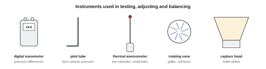
A manometer measures a pressure difference. The oldest kind is a U-tube or inclined tube of liquid, where the difference pushes the liquid up one side; an inclined tube spreads a small rise along a longer scale so that small pressures can be read. Liquid manometers need no calibration beyond levelling and zeroing and are still used as a reference, but they are fragile, slow and awkward on a ladder. Most TAB work now uses digital manometers, which read pressure electronically, show it in a choice of units, average readings over time and, with a pitot tube, convert velocity pressure directly to velocity and airflow.
A digital manometer has two ports, usually marked positive and negative or high and low. The reading is the pressure at the positive port minus the pressure at the negative. Static pressure in a supply duct is read with the duct connected to the positive port and the negative port open to the room; in a return duct, where the pressure is below the room, the reading is negative. Getting the hoses backward does not damage anything but gives a reading of the wrong sign, which is a common source of confusion in a static pressure profile.
Good practice with a digital manometer includes zeroing it with both ports open to the same air before each set of readings, keeping hoses short, clean and free of kinks and water, using the averaging function where readings fluctuate, and checking the battery. Many instruments also need the air temperature and barometric pressure entered so they can correct velocity readings for density, as lesson 2 explained.
Pitot tubes
The standard pitot-static tube is a stainless steel L-shaped probe with an opening at its tip facing into the airflow and a ring of small holes around its stem a short distance back. The tip senses total pressure, the side holes sense static pressure, and connected across a manometer the pair reads velocity pressure. Pitot tubes come in lengths to suit the duct, marked along the stem so the technician can set the traverse depths described in lesson 5. They need no calibration if they are undamaged, which is one reason they are the reference method for duct airflow; a bent tip, a blocked hole or a dent changes the reading and the tube must be replaced.
The pitot tube must point straight into the flow. A tube turned more than a few degrees off the flow reads low. It also needs a minimum velocity to give a usable reading, because the velocity pressure at low speed is too small to measure accurately. Below that limit, a thermal anemometer or another method is used instead.
Anemometers
Thermal anemometers, often called hot-wire anemometers, measure air speed directly by sensing how fast moving air cools a heated element at the probe tip. They read low velocities well, which pitot tubes cannot, and fit through small holes, which makes them useful in small ducts, at outlets and for checking airflow across door openings and through grilles. They are more sensitive to direction, temperature and dirt than pitot tubes, they read velocity at a single point, and they must be calibrated regularly. Many models also read air temperature and humidity.
Rotating vane anemometers have a small propeller in a ring, turned by the air, with the rotation converted to velocity. A large-diameter vane anemometer held against a grille or a coil face averages velocity over the vane area. Vane anemometers are used for coil face velocity, filter banks, louvres in exhaust and at return and exhaust grilles, often with a correction factor described in lesson 6. They read poorly at low velocity and should be held square to the flow.
Capture hoods and flow hoods
A capture hood, also called a flow hood or balometer, is a fabric or plastic hood that fits over a ceiling diffuser or grille, collects all the air it supplies or draws, and funnels it across a sensing grid in the base. The grid averages velocity pressure across its area and the meter converts it to airflow. A hood reads the outlet's airflow directly, in one reading, which makes it the quickest way to balance a room full of diffusers. Hoods come with tops of different sizes to fit common diffusers, typically around 600 × 600 mm, and other shapes for slots and long grilles.
Hoods have limits. The hood itself adds a small resistance to the outlet it covers, which can reduce the flow through that outlet slightly; many digital hoods have a back-pressure compensation feature that takes two readings with a flap open and closed and corrects for this. Hoods read poorly on outlets with very high or very low airflow, on outlets much larger than the hood top, and where the hood cannot seal against the ceiling. They also read differently on supply and exhaust, and must be set to the right mode. Lesson 6 covers how hood readings are taken and checked.
The TAB standards and good practice expect hood readings to be verified against a duct traverse on at least a sample of branches. If the sum of hood readings on a branch is consistently higher or lower than the traverse of that branch, a correction factor may be applied, or the method reconsidered.
Tachometers, thermometers and electrical meters
Fan and motor speeds are read with a tachometer. Contact tachometers touch the end of the shaft with a rubber tip and are used only on equipment that is locked out or where the shaft end is exposed and guarded; optical tachometers read a piece of reflective tape on the shaft or sheave from a distance and are the safer choice. Stroboscopes make a rotating sheave appear to stand still when the flash rate matches its speed, and are useful for reading speed and checking belts. Speeds from a variable-frequency drive's display are approximate and are confirmed with a tachometer.
Temperatures are read with thermometers or thermocouple probes to check supply, return and mixed air temperatures and to correct for density. Electrical readings, motor current at each phase, voltage and sometimes power, are taken with a clamp-on ammeter and a voltmeter rated for the circuit. These are live readings and are taken only by trained workers following the employer's electrical safety program, as lesson 1 noted. Lesson 9 shows how they are used to estimate motor load.
Calibration
Every instrument except a liquid manometer and an undamaged pitot tube drifts with time and use. TAB standards require instruments to be calibrated at set intervals, commonly within the past year for electronic instruments and more often if they are dropped or give doubtful readings, by a laboratory traceable to national standards. The calibration certificate records the date, the instrument's serial number and how far it read from the reference. A TAB report lists every instrument used, its serial number and its calibration date, and a reviewer who finds an expired calibration can reject the report.
In Canada, traceability is to the national measurement standards maintained by the National Research Council, usually through a calibration laboratory accredited by the Standards Council of Canada or another recognized accreditor. Keelson sends its hoods and manometers to an accredited lab each spring, before the summer school retrofits.
Between calibrations, technicians do field checks. Two manometers connected to the same pressure should agree; a hood reading on a diffuser should agree reasonably with a traverse of the duct feeding it; a thermal anemometer can be compared with a pitot reading at a velocity where both work. Any instrument that fails a field check is taken out of service until it is recalibrated.
# Instrument check: compare a working instrument with the reference and see whether the error fits its stated accuracy
ref = [60, 120, 240, 480]        # reference readings, L/s
test = [62, 124, 251, 470]       # working instrument, same points
spec_pct = 3.0     # stated accuracy, percent of reading
spec_abs = 2.0   # plus a fixed allowance, L/s
for r, t in zip(ref, test):
    err = t - r
    allow = spec_pct / 100 * r + spec_abs
print(f"ref {r} L/s, read {t} L/s, error {err:+.1f}, allowed {allow:.1f} ->", "OK" if abs(err) <= allow else "out of tolerance")ref 60 L/s, read 62 L/s, error +2.0, allowed 3.8 -> OK ref 120 L/s, read 124 L/s, error +4.0, allowed 5.6 -> OK ref 240 L/s, read 251 L/s, error +11.0, allowed 9.2 -> out of tolerance ref 480 L/s, read 470 L/s, error -10.0, allowed 16.4 -> OK
In this example the hood reads within its stated accuracy at three points but not at the third, where it reads high by more than its allowance. That does not mean the hood is useless; it may mean the hood reads poorly in that range, or that the reference was disturbed. Marisol's rule is that a failed check means the instrument goes back to the lab and the readings it took that day are repeated.
Accuracy and uncertainty
No instrument reads exactly, and the TAB technician has to understand how much a reading can be trusted. Instrument accuracy is usually stated as a percentage of reading plus a fixed amount, and it is worse at the low end of the range. Field conditions add more uncertainty: turbulent flow near fittings, pitot tubes not quite square to the flow, a hood that does not seal, fluctuating readings from a fan. TAB procedures reduce these effects by choosing good measurement locations, taking enough readings, averaging and repeating, and checking that readings make sense together. The sum of the outlet flows on a branch should be close to the branch traverse; the branch traverses should add up to the main; and the main should match the fan.
When the numbers do not add up, the technician looks for the reason rather than forcing them to. Duct leakage between the traverse and the outlets, an outlet that was missed, a wrong area, a hood used outside its range or an instrument problem can all show up as a mismatch, and finding which one it is often reveals a real problem in the system.
Worked problem
Choosing instruments for the Eastgate isolation suite
Kai has to measure the exhaust from an isolation room through a 300 × 300 mm ceiling grille drawing about 150 L/s, and the airflow through the 10 mm gap under the room's door. Which instruments should he use?
Show solution
- For the grille: a capture hood with a top that fits the grille, set to exhaust mode, with back-pressure compensation on.
- Confirm with a pitot traverse of the exhaust branch duct if it has a straight run, because the room's pressure relationship depends on the exhaust.
- For the door gap: the velocity is low and the opening is narrow, so a thermal anemometer, read at several points along the gap.
- Record the room pressure difference with a digital manometer, tube under the door, as the main check of the relationship.
Answer: Each instrument is used where it reads well: hood at the grille, pitot in the duct, thermal anemometer at low velocity, manometer for the pressure difference.
Common mistakes
MistakeUsing an instrument past its calibration date.
InsteadCheck certificates before the job and keep a calibrated set in each case.
MistakeReading static pressure with the hoses reversed and not noticing.
InsteadKnow which port is which and check the sign makes sense.
MistakeUsing a pitot tube where the velocity is too low to read.
InsteadUse a thermal anemometer at low velocities.
MistakeForcing hood readings to match the design.
InsteadCheck them against a branch traverse and find the reason for any mismatch.
MistakeReading a shaft with a contact tachometer near an open guard on a running fan.
InsteadUse an optical tachometer or lock out the unit.
Summary and key terms
- Digital manometers read pressure differences; zero them, know the ports and keep hoses clean.
- Pitot tubes are the reference for duct airflow but need enough velocity and good alignment.
- Thermal anemometers read low velocities at a point; vane anemometers average over an area.
- Capture hoods read outlet airflow directly but have range, fit and back-pressure limits.
- Tachometers, thermometers and electrical meters support fan and motor checks.
- Instruments are calibrated at set intervals with traceable certificates, and field-checked between.
- Digital manometer
- An electronic instrument that reads the pressure difference between two ports.
- Thermal anemometer
- An instrument that reads air speed from the cooling of a heated sensor.
- Rotating vane anemometer
- An instrument with a small propeller that reads air speed over its area.
- Capture hood
- A hood placed over an outlet to read its airflow directly.
- Calibration
- Comparing an instrument with a traceable reference and recording its error.
- Back-pressure compensation
- A hood feature that corrects for the hood's own resistance at the outlet.
Practice problems
Work each problem on paper first, then reveal the answer to check.
Why does a pitot tube need no regular calibration?
Show answer
Its reading depends only on its geometry; if it is undamaged and clean, it reads correctly.
Name one strength and one weakness of a thermal anemometer.
Show answer
It reads low velocities and fits small holes; it reads at one point and must be calibrated.
What should a TAB report say about each instrument?
Show answer
Its type, serial number and calibration date.
The outlet readings on a branch add up to 20 percent more than the branch traverse. Name two possible causes.
Show answer
Any two of: a hood reading high, the wrong duct area, a missed bend in the traverse, a leak upstream of the traverse, an outlet counted twice.
Lesson quiz · 5 questions
Score 60% or more to complete this lesson.
Create a free account to save your progress, take quizzes and earn a certificate.